Removal and Installation
| caution | Bumper fascia is made of resin. Never apply strong force to it, and be careful to prevent contact with oil. |
REMOVAL
1. Fully open power liftgate.
2. Remove rear combination light (body side). Refer to Removal and Installation .
.
 .
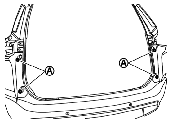
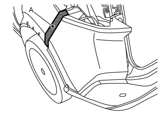
.3. Remove rear fillet molding rear. Refer to Removal and Installation .
.
 .
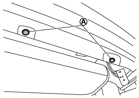
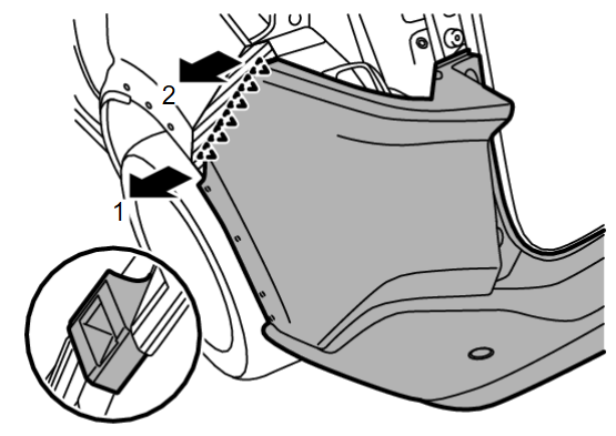
.9. Pull rear bumper fascia side toward the vehicle side to disengage the fitting of rear bumper side bracket and rear bumper fascia side according to the numerical order 1→2 as shown by the arrows in the figure.
| caution | When removing rear bumper fascia, 2 workers are required so as to prevent it from dropping. |
 | : Pawl |
10. Disconnect harness connectors.
11. Remove rear bumper fascia.
| caution | When removing rear bumper fascia, 2 workers are required so as to prevent it from dropping. |
12. Remove the following parts after removing rear bumper fascia.
- Hands free sensor control unit (if equipped). Refer to Removal and Installation
 .
. - Rear sonar sensor. Refer to Removal and Installation
 .
. - Reflex reflector. Refer to Removal and Installation
 .
. - Rear bumper bracket
- Rear bumper fascia LH and RH
- Rear bumper finisher
- Rear bumper molding
- Rear bumper cover
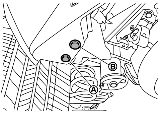
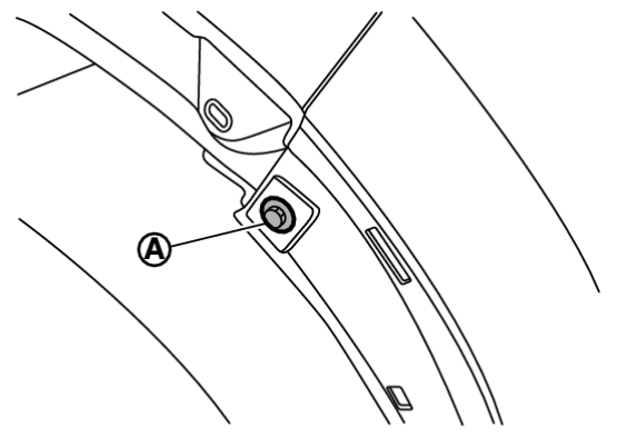
13. Remove rear bumper side bracket fixing screws and pawl, and then remove rear bumper side bracket.
14. Remove rear bumper reinforcement mounting nuts, and then remove rear bumper reinforcement.
15. Remove rear bumper stay mounting bolts, and then remove rear bumper stay.
INSTALLATION
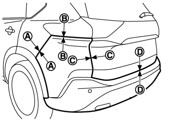
Note the following items, and then install in the reverse order of removal.
| note |
| |||||||||||||||||||
![[Previous]](../../../buttons/fprev.png)
![[Next]](../../../buttons/fnext.png)
 .
.
 .
.
 –
–  –
–