DTC No.B1031: Air thermo sensor circuit low
DTC No.B1032: Air thermo sensor circuit high
DTC No.B1032: Air thermo sensor circuit high
DTC SET CONDITION
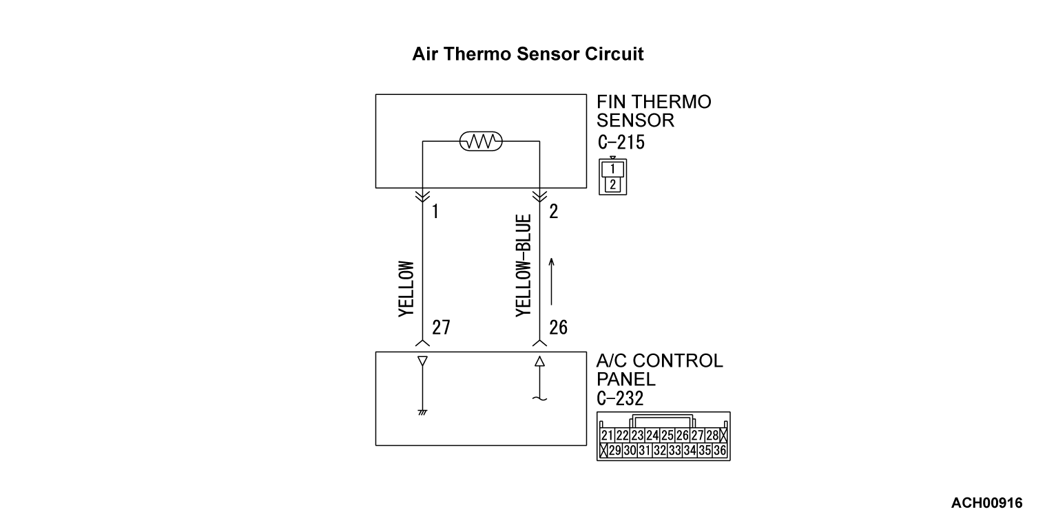
- DTC B1031 is set if there is a short circuit in the air thermo sensor input circuit.
- DTC B1032 is set if there is a defective connector connection, or if there is an open circuit in the harness.
TECHNICAL DESCRIPTION (COMMENT)
Current trouble
- The A/C control panel, the air thermo sensor, or connector(s) or wiring between the two may be defective.
Past trouble
- If DTC B1031 or B1032 is set as a past trouble, carry out diagnosis with particular emphasis on wiring and connector(s) between the A/C control panel and the air thermo sensor. If the connectors and wiring are normal, and obviously the ECU is the cause of the trouble, replace the ECU. If in doubt, do not replace the ECU.
TROUBLESHOOTING HINT
- Malfunction of connector.
- Malfunction of the harness.
- Malfunction of the air thermo sensor.
- Malfunction of the A/C control panel.
DIAGNOSIS
Required Special Tool:
- MB991223: Harness Set
- MB992006: Extra Fine Probe
STEP 1. Using scan tool MB991958, diagnose the CAN bus line
(1)
| caution | To prevent damage to scan tool MB991958, always turn the ignition switch to the "LOCK" (OFF) position before connecting or disconnecting scan tool MB991958. |
(2) Turn the ignition switch to the "ON" position.
(3) Diagnose the CAN bus line.
(4) Turn the ignition switch to the "LOCK" (OFF) position.
Is the CAN bus line found to be normal?
STEP 2. Recheck for diagnostic trouble code.
Recheck if the DTC is set.
(1) Erase the DTC.
(2) Turn the ignition switch to "ON" position.
(3) Check if the DTC is set.
Is the DTC set?
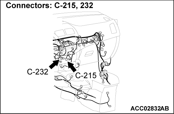
STEP 3. Check air thermo sensor connector C-215 and A/C control panel connector C-232 for loose, corroded or damaged terminals, or terminals pushed back in the connector.
Are air thermo sensor connector C-215 and A/C control panel connector C-232 in good condition?
STEP 4. Check the wiring harness between A/C control panel connector C-232 (terminals No.26 and 27) and air thermo sensor connector C-215 (terminals No.2 and 1).
- Check the sensor signal line and ground line for open and short circuit.
Is the wiring harness between A/C control panel connector C-232 (terminals No.26 and 27) and air thermo sensor connector C-215 (terminals No.2 and 1) in good condition?
 Repair the wiring harness.
STEP 5. Check the air thermo sensor.
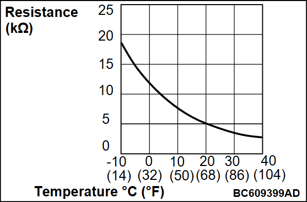
Measure the resistance between connector terminals No.1 and 2 under at least two different temperatures. The resistance values should generally match those in the graph.
| note | The temperature at the check should not exceed the range in the graph. |
Is the air thermo sensor in good condition?
STEP 6. Recheck for diagnostic trouble code.
Check again if the DTC is set. The procedure is complete.
(1) Connect scan tool MB991958 to the data link connector
(2) Turn the ignition switch to the "ON" position.
(3) Check if the DTC is set.
(4) Turn the ignition switch to the "LOCK" (OFF) position.
Is the DTC set?
 The procedure is complete.
![[Previous]](../../../buttons/fprev.png)
![[Next]](../../../buttons/fnext.png)


