DTC C2324 Mirror indicator disconnection
| caution | Before replacing the ECU, ensure that the input and output signal circuits are normal. |
OPERATION
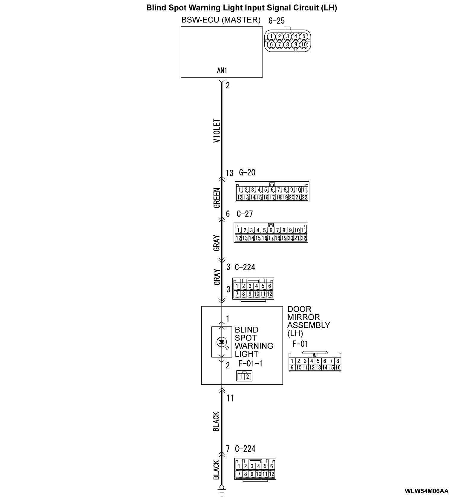
The BSW-ECU (master) energizes and controls the blind spot warning light (LH), which is integrated in the door mirror assembly.
CHECK CONDITION
When all of the conditions below are satisfied:
- Ignition switch is in the ON position.
- BSW-ECU (master) system voltage is at 9 to 16 volts.
DIAGNOSTIC FUNCTION AND JUDGMENT CRITERIA
The BSW-ECU (master) will set DTC C2324 when all of the following conditions are satisfied:
- The blind spot warning light (LH) is energized
- BSW-ECU (master) terminal No.3 voltage measures 5.9 volts or more
- BSW-ECU (master) terminal No.3 circuit current measures less than 3.0 mA
TROUBLESHOOTING HINTS
- The blind spot warning light within the door mirror assembly (LH) may be defective
- The BSW-ECU (master) may be defective
- The wiring harness or connectors may have loose, corroded, or damaged terminals, or terminals pushed back in the connector
DIAGNOSIS
Required Special Tools:
- MB991223: Harness Set
- MB992006: Extra Fine Probe
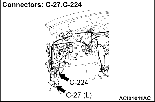
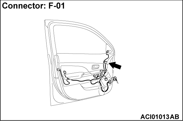
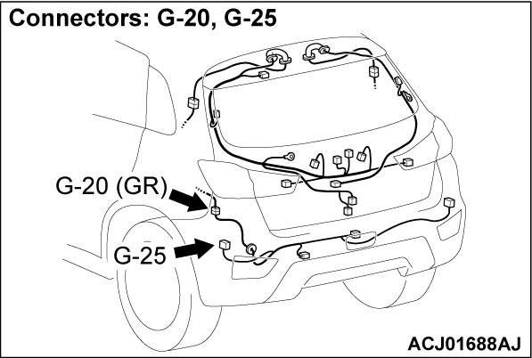
STEP 1. Connectors check: door mirror assembly (LH) (incorporating blind spot warning light) connector F-01, BSW-ECU (master) connector G-25.
Are door mirror assembly (LH) (incorporating blind spot warning light) connector F-01 and BSW-ECU (master) connector G-25 in good condition?
 The wiring harness may be damaged or the connector(s) may have loose, corroded or damaged terminals, or terminals pushed back in the connector. Repair the wiring harness as necessary.
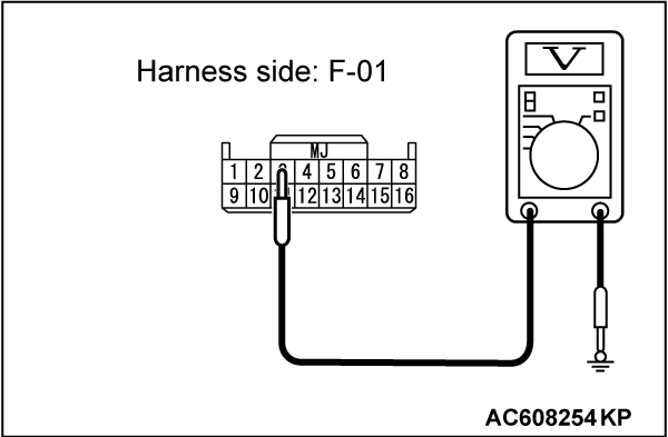
STEP 2. Perform voltage measurement at door mirror assembly (LH) (incorporating blind spot warning light) connector F-01.
(1) Disconnect the door mirror assembly (LH) connector F-01, and measure at the wiring harness side.
(2) Turn the ignition switch from "LOCK" (OFF) position to "ON" position.
(3) Check the voltage between the door mirror assembly (LH) connector F-01 (terminal No.3) and body ground.
(1) When the actuator test (Item No. 1) is executed.
OK: 6 volts or more
(2) When the actuator test (Item No. 1) is aborted.
OK: 1 volts or less
Is the check result normal?
STEP 3. Check the wiring harness between BSW-ECU (master) connector G-25 terminal No. 2 and door mirror assembly (LH) (incorporating blind spot warning light) connector F-01 (terminal No. 3).
- Check the power supply line for open circuit.
Is the wiring harness between BSW-ECU (master) connector G-25 (terminal 2) and door mirror assembly (LH) (incorporating blind spot warning light) connector F-01 (terminal 3) in good condition?
 Replace the BSW-ECU (master).
 The wiring harness may be damaged or the connector(s) may have loose, corroded or damaged terminals, or terminals pushed back in the connector. Repair the wiring harness as necessary.
STEP 4. Check the wiring harness between door mirror assembly (LH) (incorporating blind spot warning light) connector F-01 (terminal No. 11) and body ground.
- Check the ground line for ground circuit.
Is the wiring harness between door mirror assembly (LH) (incorporating blind spot warning light) connector F-01 (terminal No. 11) and body ground in good condition?
 The wiring harness may be damaged or the connector(s) may have loose, corroded or damaged terminals, or terminals pushed back in the connector. Repair the wiring harness as necessary.
STEP 5. Check the door mirror assembly (LH) (incorporating blind spot warning light).
STEP 6. Check the blind spot warning light (LH) on mirror.
Refer to GROUP 51 - Door Mirror Inspection  .
. Repair the door mirror main harness (LH).
 Replace the mirror (LH).
 .
.Is the check result normal?
 Repair the door mirror main harness (LH).
 Replace the mirror (LH).
STEP 7. Check whether the DTC is set again.
Check again if the DTC is set in the BSW-ECU (master). Replace the BSW-ECU (master).
(1)
| caution | To prevent damage to scan tool (M.U.T.-III), always turn the ignition switch to the "LOCK" (OFF) position before connecting or disconnecting scan tool (M.U.T.-III). |
(2) Erase the DTC.
(3) Turn the ignition switch from the "LOCK" (OFF) position to the "ON" position.
(4) Check if the DTC is set.
Is the DTC set?
 Replace the BSW-ECU (master).
![[Previous]](../../../buttons/fprev.png)
![[Next]](../../../buttons/fnext.png)
