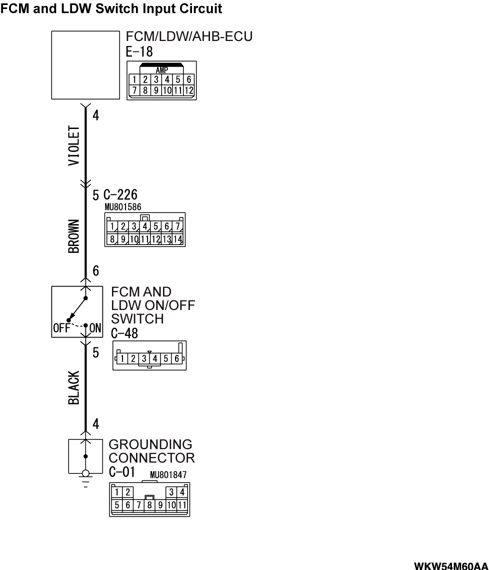
DTC C1705: LDW SW circuit low (short)
| caution |
|
TROUBLE JUDGMENT
When the FCM/LDW/AHB-ECU receives "ON" signal from the FCM and LDW ON/OFF switch for at least one minute consecutively, DTC No. C1705 will be set.
JUDGMENT CRITERIA
The FCM/LDW/AHB-ECU receives a signal from the FCM and LDW ON/OFF switch. When the ECU receives "ON" signal from the FCM and LDW ON/OFF switch for at least one minute consecutively, it determines that the system is defective.
TROUBLESHOOTING HINTS
- The FCM and LDW ON/OFF switch (Stuck on) may be defective
- The FCM/LDW/AHB-ECU may be defective
- The wiring harness or connectors may have loose, corroded, or damaged terminals, or terminals pushed back in the connector
DIAGNOSIS
STEP 1. Check the FCM and LDW ON/OFF switch.
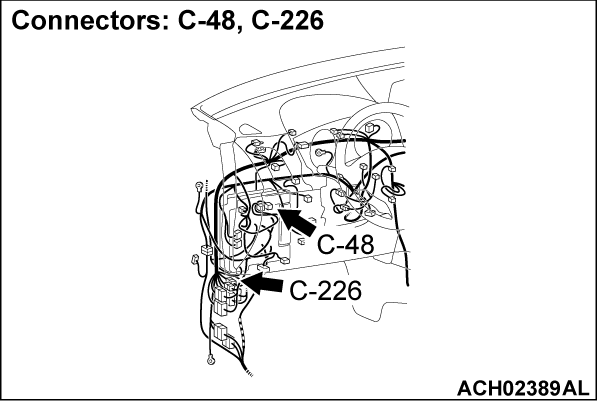
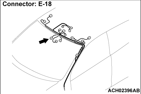
STEP 2. Check FCM and LDW ON/OFF switch connector C-48, FCM/LDW/AHB-ECU connector E-18 for loose, corroded or damaged terminals, or terminals pushed back in the connector.
Is FCM and LDW ON/OFF switch connector C-48, FCM/LDW/AHB-ECU connector E-18 in good condition?
STEP 3. Check the wiring harness between FCM and LDW ON/OFF switch connector C-48 (terminal 6) and FCM/LDW/AHB-ECU connector E-18 (terminal 4).
Check the input line for short and open circuit. The wiring harness may be damaged or the connector(s) may have loose, corroded or damaged terminals, or terminals pushed back in the connector. Repair the wiring harness as necessary.
Is the check result normal?
 The wiring harness may be damaged or the connector(s) may have loose, corroded or damaged terminals, or terminals pushed back in the connector. Repair the wiring harness as necessary.
STEP 4. Using scan tool (M.U.T.-III), check data list.
(1)
| caution | To prevent damage to scan tool (M.U.T.-III), always turn the ignition switch to the "LOCK" (OFF) position before connecting or disconnecting scan tool (M.U.T.-III). |
(2) Check the FCM/LDW/AHB-ECU data list (Refer to  ).
).
 ).
).- When the FCM and LDW ON/OFF switch is pressed.
|
- When the FCM and LDW ON/OFF switch is not pressed.
|
OK: Normal condition is displayed.
Is the check result normal?
STEP 5. Check whether the DTC is set again.
Check again if the DTC is set in the FCM/LDW/AHB-ECU.
(1) Erase the DTC.
(2) Turn the ignition switch from "LOCK" (OFF) position to "ON" position.
(3) Check if DTC is set.
Is the DTC set?
![[Previous]](../../../buttons/fprev.png)
![[Next]](../../../buttons/fnext.png)


