Inspection Procedure 1: Power Supply Circuit Check
TECHNICAL DESCRIPTION (COMMENT)
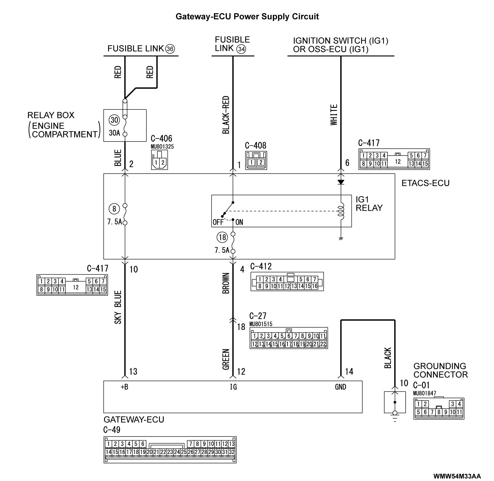
If the gateway-ECU functions do not work at all, power supply to the gateway-ECU, or the gateway-ECU itself may have a problem.
TROUBLESHOOTING HINTS
- The wiring harness or connectors may have loose, corroded, or damaged terminals, or terminals pushed back in the connector
- Malfunction of gateway-ECU
DIAGNOSIS
Required Special Tools:
- MB991223: Harness Set
- MB992006: Extra Fine Probe
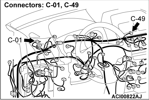
STEP 1. Check gateway-ECU connector C-49 for loose, corroded or damaged terminals, or terminals pushed back in the connector.
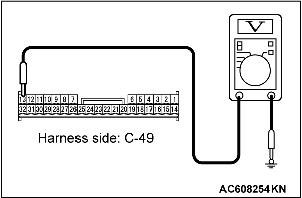
STEP 2. Measure the voltage at gateway-ECU connector C-49.
(1) Disconnect the gateway-ECU connector C-49, and measure at the wiring harness side.
(2) Turn the ignition switch to the "LOCK" (OFF) position.
(3) Measure the voltage between the gateway-ECU connector C-49 terminal No. 13 and the body ground.
- The voltage should measure approximately 12 volts (battery positive voltage).
Is the measured voltage approximately 12 volts (battery positive voltage)?
STEP 3. Check the wiring harness between the battery (fusible link No. 36) and gateway-ECU connector C-49 terminal No. 13.
Check the power supply line for open circuit. Perform the battery test (Refer to GROUP 54A, Battery Test
  ) or check the battery terminals for looseness or contamination.
 Repair the wiring harness.
Is the check result normal?
 Perform the battery test (Refer to GROUP 54A, Battery Test
  ) or check the battery terminals for looseness or contamination.
 Repair the wiring harness.
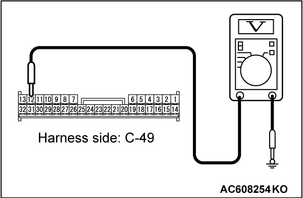
STEP 4. Measure the voltage at gateway-ECU connector C-49.
(1) Disconnect the gateway-ECU connector C-49, and measure at the wiring harness side.
(2) Turn the ignition switch to the "ON" position.
(3) Measure the voltage between the gateway-ECU connector C-49 terminal No. 12 and the body ground.
- The voltage should measure approximately 12 volts (battery positive voltage).
Is the measured voltage approximately 12 volts (battery positive voltage)?
STEP 5. Using scan tool MB991958, check other system data list.
Check the input signal from the ignition switch (IG1) in the ETACS-ECU.
- Turn the ignition switch to the "ON" position.
|
Do the scan tool MB991958 display the item "IG voltage" is normal condition?
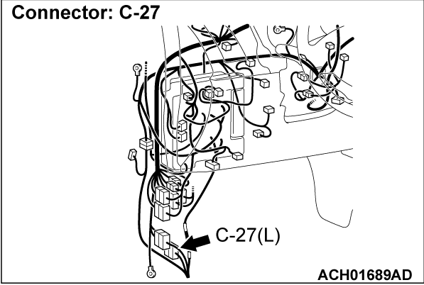
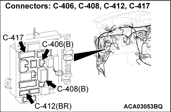
STEP 6. Check the wiring harness between the IG1 relay and gateway-ECU connector C-49 terminal No. 12.
Check the power supply line for open circuit. The trouble can be an intermittent malfunction (Refer to GROUP 00, How to Use Troubleshooting/Inspection Service Points - How to Cope with Intermittent Malfunction
  ).
). Repair the wiring harness.
Is the check result normal?
 The trouble can be an intermittent malfunction (Refer to GROUP 00, How to Use Troubleshooting/Inspection Service Points - How to Cope with Intermittent Malfunction
  ).
). Repair the wiring harness.
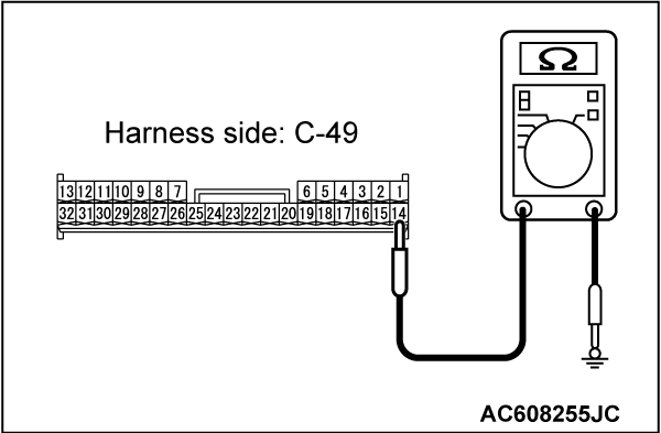
STEP 7. Measure the resistance at gateway-ECU connector C-49.
(1) Disconnect the gateway-ECU connector C-49, and measure at the wiring harness side.
(2) Measure the resistance between the gateway-ECU connector C-49 terminal No. 14 and the body ground.
- The resistance should be 2 ohms or less.
Is the measured resistance 2 ohms or less?
STEP 8. Check the wiring harness between the gateway-ECU connector C-49 terminal No. 14 and body ground.
Check the ground wires for open circuit. The trouble can be an intermittent malfunction (Refer to GROUP 00, How to Use Troubleshooting/Inspection Service Points - How to Cope with Intermittent Malfunction
  ).
). Repair the wiring harness.
Is the check result normal?
 The trouble can be an intermittent malfunction (Refer to GROUP 00, How to Use Troubleshooting/Inspection Service Points - How to Cope with Intermittent Malfunction
  ).
). Repair the wiring harness.
![[Previous]](../../../buttons/fprev.png)
![[Next]](../../../buttons/fnext.png)
