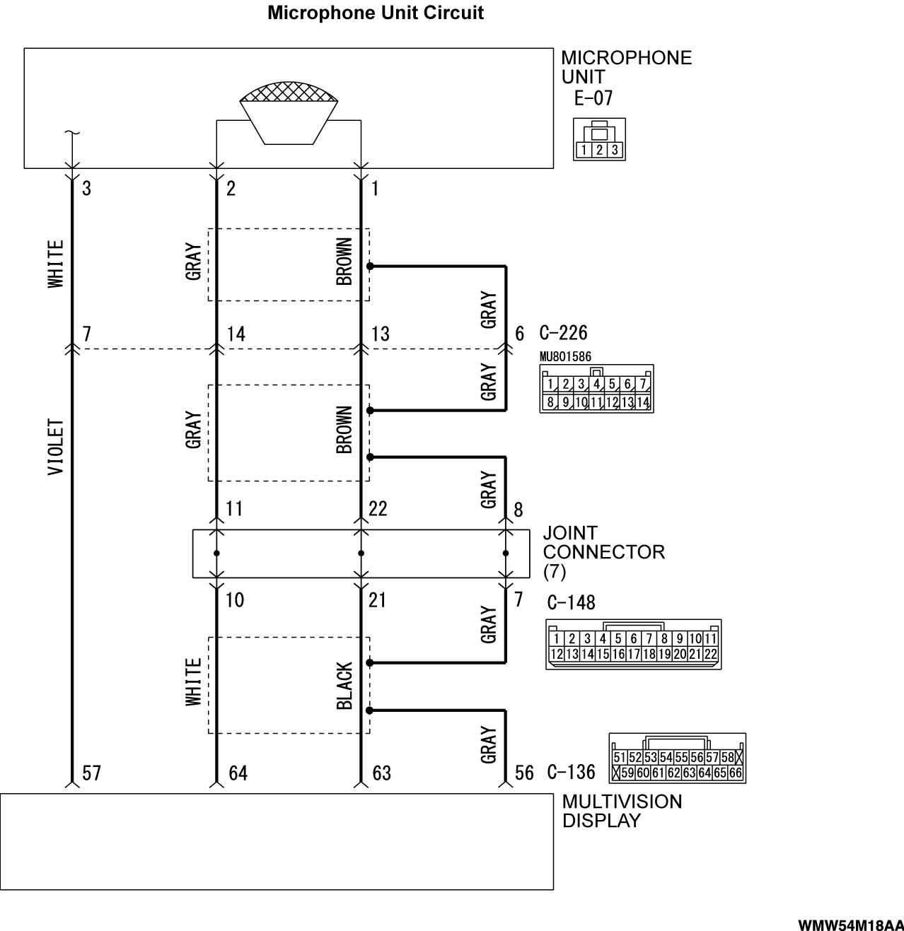
Inspection Procedure 8: The microphone does not respond to your voice normally.
| caution | Before replacing the multivision display, ensure that the power supply circuit, the ground circuit and the communication circuit are normal. |
TECHNICAL DESCRIPTION (COMMENT)
If the microphone does not respond to your voice normally, the microphone or multivision display may be defective.
TROUBLESHOOTING HINTS
- The multivision display may be defective
- The microphone unit may be defective
- The wiring harness or connectors may have loose, corroded, or damaged terminals, or terminals pushed back in the connector
DIAGNOSIS
Required Special Tools:
- MB991223: Harness Set
- MB992006: Extra Fine Probe
STEP 1. Check if the error message is displayed on the multivision display.
STEP 2. Check the service data for multivision display.
Perform "Communications & Connection Check" in the diagnosis mode to check that the communication and wire connection with the microphone are connected (Refer to  ).
).
 ).
).Is the check result normal?
STEP 3. Check the microphone for multivision display.
Using the multivision display diagnosis mode, check if the "Mic" (Refer to  ).
).
 ).
).OK: Confirm that "Mic Level" changes when you speak to the microphone.
Is the check result normal?
STEP 4. Replace the microphone unit temporarily, and check the trouble symptom.
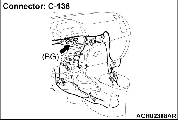
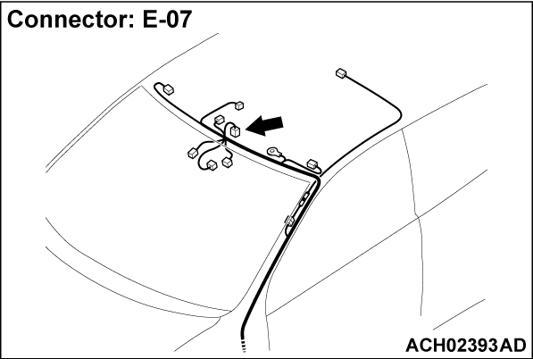
STEP 5. Check microphone unit connector E-07 and multivision display connector C-136 for loose, corroded or damaged terminals, or terminals pushed back in the connector.
Are microphone unit connector E-07 and multivision display connector C-136 in good condition?
STEP 6. Check the wiring harness between microphone unit connector E-07 (terminal 1, 2, 3) and multivision display connector C-136 (terminal 63, 64, 57).
- Check the signal lines for open circuit and short circuit.
Is the wiring harness between microphone unit connector E-07 (terminal 1, 2, 3) and multivision display connector C-136 (terminal 63, 64, 57) in good condition?
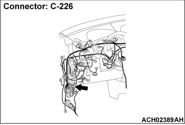
 The wiring harness may be damaged or the connector(s) may have loose, corroded or damaged terminals, or terminals pushed back in the connector. Repair the wiring harness as necessary.
![[Previous]](../../../buttons/fprev.png)
![[Next]](../../../buttons/fnext.png)


