DIAGNOSIS MODE
HOW TO INITIATE THE DIAGNOSIS MODE
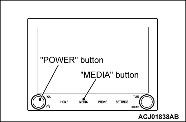
1. Press and hold the power button and "MEDIA" button for three seconds.
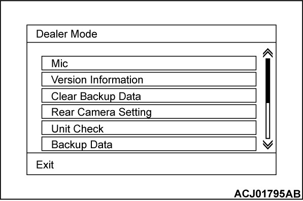
2. The "Dealer Mode" screen, i.e. top screen of the diagnosis mode is displayed.
HOW TO TERMINATE THE DIAGNOSIS MODE
If the operations below are done, the diagnosis mode will be terminated.
- You press the "Exit" button while lower left of the "Dealer Mode" screen is displayed.
DIAGNOSIS MODE ITEM
The following items can be checked or set in the diagnosis mode.
- Mic
- Version Information
- Clear Backup Data
- Rear Camera Setting
- Unit Check
- Backup Data
- Restore Data
- Touch Panel Calibrate
- Touch Panel Check
- GPS Diagnosis
- GYRO Diagnosis
- Communications & Connection Check
- Hardware Key Test
- Vehicle Status
- Radio
- Speaker Check
- CAN Check
- Display
- Log
- ILL Duty
- SiriusXM Diag mode
Mic
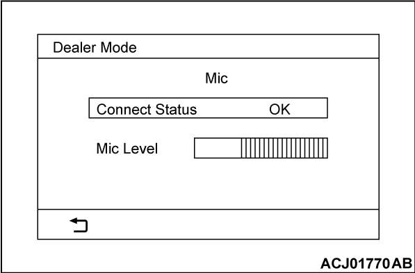
Check the microphone.
1. Select "Mic" button on "Dealer Mode" screen.
2. Confirm that "Mic Level" changes when you speak to the microphone.
Version Information
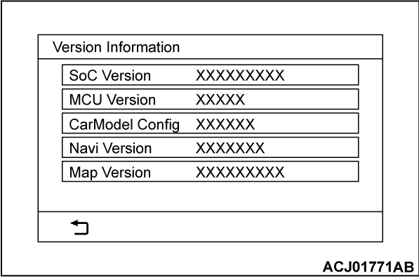
Displays the version information of the hardware, software, and database.
1. Select "Version Information" button on "Dealer Mode" screen.
2. The information you set on "Version Information" screen will be displayed.
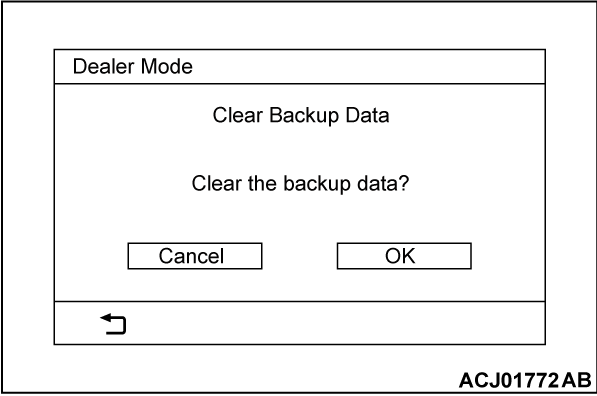
Clear Backup Data
Clears the backup data.
1. Select "Clear Backup Data" button on "Dealer Mode" screen.
2. Press the "OK" button to clear the backup data. After the backup data is cleared, the multivision display will be restarted.
Rear Camera Setting
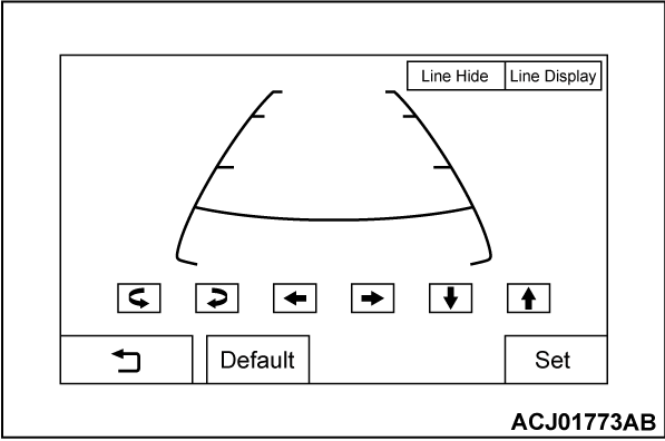
Adjusts the guideline.
1. Select "Rear Camera Setting" button on "Dealer Mode" screen.
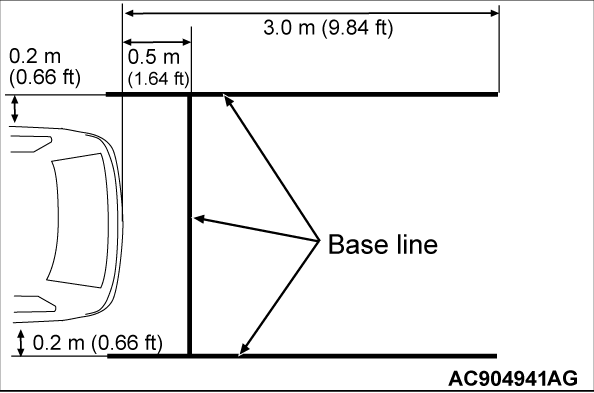
2. Draw base lines 0.5 m (1.64 ft) behind the vehicle and width +0.4 m (1.31 ft) [+0.2 m (0.66 ft) each for right and left] and align the guide line over the base lines.
3. Adjust the guide line by operating screen buttons.
4. Press the "Set" button to save the setting.
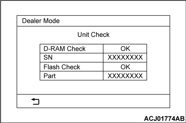
Unit Check
Displays the self-diagnosis result and information of the multivision display.
1. Select "Unit Check" button on "Dealer Mode" screen.
2. The information you set on "Unit Check" screen will be displayed.
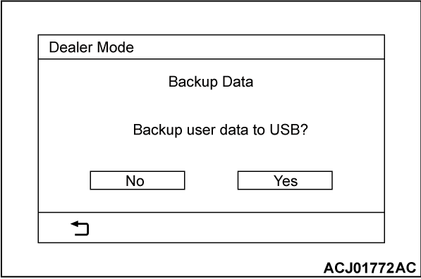
Backup Data
Backs up the user data to the USB flash drive.
1. Connect the USB flash drive to the USB adapter.
2. Select "Backup Data" button on "Dealer Mode" screen.
3. Press the "Yes" button to start the backup. After the backup is complete, the screen will return to the "Dealer Mode."
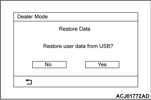
Restore Data
Restores the user memory backed up to the USB flash drive.
1. Connect the USB flash drive to the USB adapter.
2. Select "Restore Data" button on "Dealer Mode" screen.
3. Press the "Yes" button to start the restoring process. After the restoring is complete, the multivision display will be restarted.
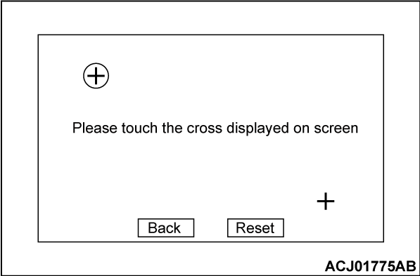
Touch Panel Calibrate
Calibrates the touch panel.
1. Select "Touch Panel Calibrate" button on "Dealer Mode" screen.
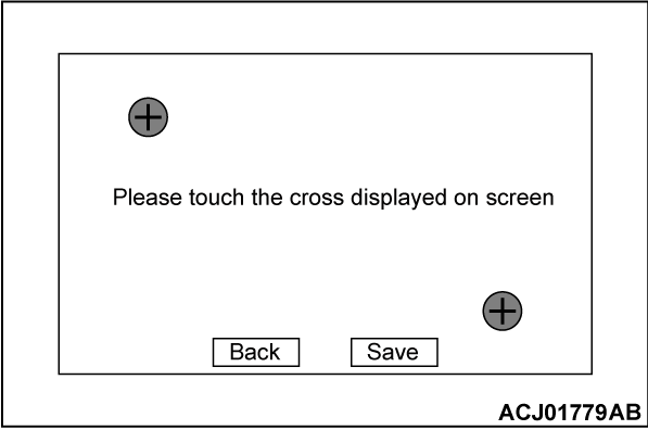
2. Click the base point in sequence.
3. Press the "Save" button and the calibration will be complete. When the message window is displayed, press the "OK" button. Then, the screen will return to "Dealer Mode."
Touch Panel Check
Check the touch panel.
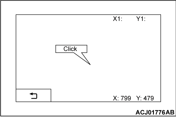
1. Select "Touch Panel Check" button on "Dealer Mode" screen.
2. The coordinates of the position at which the touch panel is clicked and the "Click" popup will be displayed.
GPS Diagnosis
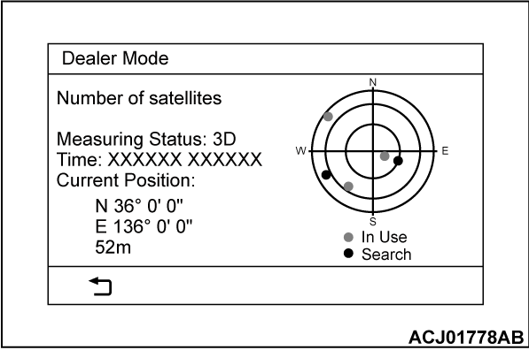
Displays the GPS-related information.
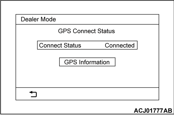
1. Select "GPS Diagnosis" button on "Dealer Mode" screen.
2. Select "GPS Information" button on "GP Connect Status" screen.
3. The GPS-related information will be displayed.
GYRO Diagnosis
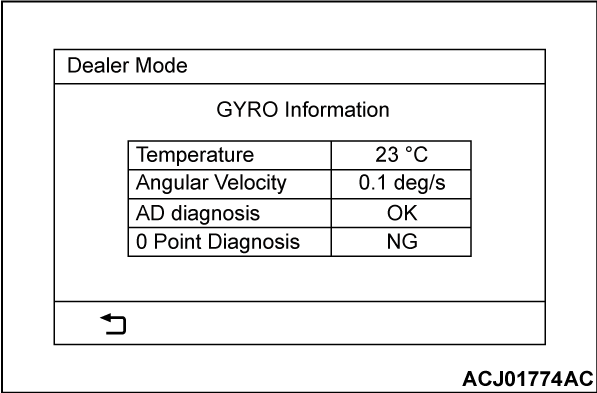
Displays the self-diagnosis result and information of the gyro sensor.
1. Select "GYRO Diagnosis" button on "Dealer Mode" screen.
2. The information you set on "GYRO Diagnosis" screen will be displayed.
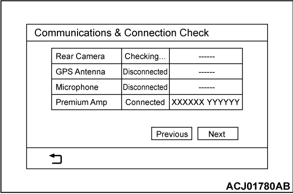
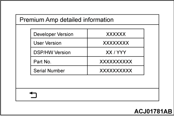
Communications & Connection Check
Check the connection status of each device.
1. Select "Communications & Connection Check" button on "Dealer Mode" screen.
2. The information you set on "Communications & Connection Check" screen will be displayed.
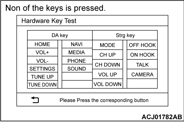
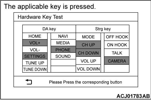
Hardware Key Test
Check the hardware key of the multivision display and steering wheel audio remote control switch.
1. Select "Hardware Key Test" button on "Dealer Mode" screen.
2. The list of hardware keys will be displayed on the "Hardware Key Test" screen, and it shows which keys are pressed.
| note |
|
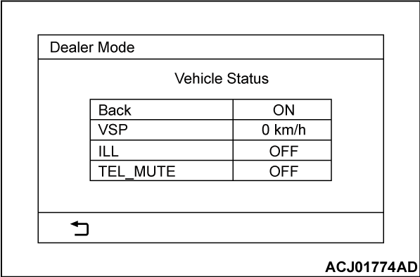
Vehicle Status
Displays statuses of vehicle signal.
1. Select "Vehicle Status" button on "Dealer Mode" screen.
2. The information you set on "Vehicle Status" screen will be displayed.
|
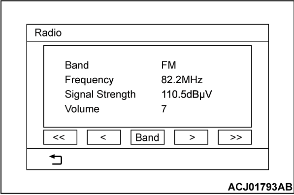
Radio
Displays the information on broadcasting method.
1. Select "Radio" button on "Dealer Mode" screen.
2. The information you set on "Radio" screen will be displayed.
3. Select "Band" button, and the available broadcasting method will be displayed in sequence.
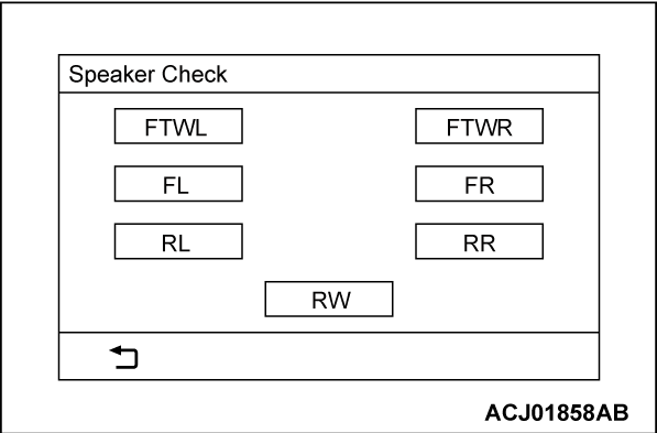
Speaker Check
Checks the speakers.
1. Select "Speaker Check" button on "Dealer Mode" screen.
2. Select a speaker to be checked, and play test tone through the speaker.
|
| note |
|
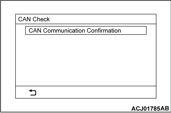
CAN Check
Displays which CAN-compatible unit is connected with the multivision display.
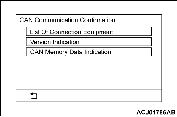
1. Select "CAN Check" button on "Dealer Mode" screen.
2. Select "CAN Communication Confirmation" button on "CAN Check" screen.
3. The following items can be checked in the "CAN Communication Confirmation" screen.
- List Of Connection Equipment
- Version Indication
- CAN Memory Data Indication
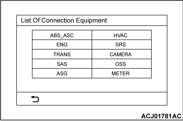
<List Of Connection Equipment>
1. Select "List Of Connection Equipment" button on "CAN Communication Confirmation" screen.
2. The system will search device(s), which are connected via CAN, and display the list of the devices.
|
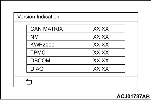
<Version Indication>
1. Select "Version Indication" button on "CAN Communication Confirmation" screen.
2. A version information will be displayed.
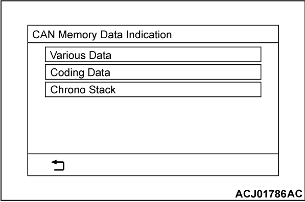
<CAN Memory Data Indication>
1. Select "CAN Memory Data Indication" button on "CAN Communication Confirmation" screen.
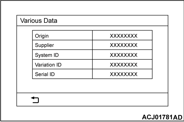
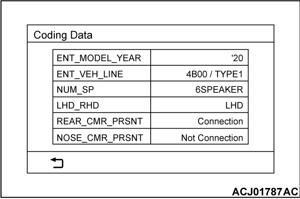
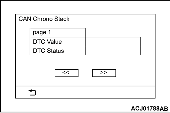
2. "CAN Memory Data Indication" will be displayed. A respective data will be displayed by selecting each button ("Various Data", "Coding Data", "Chrono Stack").
- Select "Various Data."
- Select "Coding Data."
- Select "Chrono Stack."
Display
Check the display.
1. Select "Display" button on "Dealer Mode" screen.
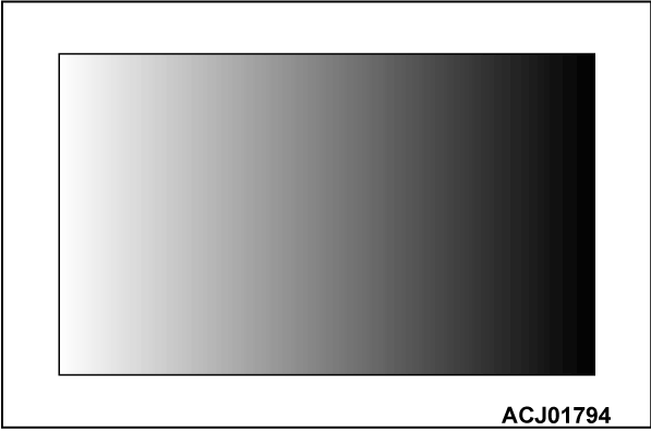
2. The display check screen will be displayed in the following order. Tap the screen to proceed to the next screen. After the last screen is displayed, the screen will return to the "Dealer Mode."
- Gradient grayscale pattern screen
- Full-scale white screen
- Color bars screen
- Cross-hatch pattern screen
- Monocolor vertical stripe screen
- Full-scale black screen
- Full-scale red screen
- Full-scale green screen
- Full-scale blue screen
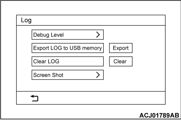
Log
Performs the setting of the event log and the operation of the event log data.
1. Select "Log" button on "Dealer Mode" screen.
2. The following items will be the "Log" screen.
- Debug Level
- Export LOG to USB memory
- Clear LOG
- Screen Shot
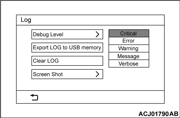
<Debug Level>
1. Select "Debug Level" button on "Log" screen.
2.
When the sub menu is displayed, select the debug level.
| caution |
|
<Export LOG to USB memory>
1. Connect the USB flash drive to the USB adapter.
2. Press the "Export" button. The export will be started, and a log will be saved in the USB flash drive.
3. A message window is displayed. Select "OK" button.
<Clear LOG>
Press the "Clear" button to clear the log.
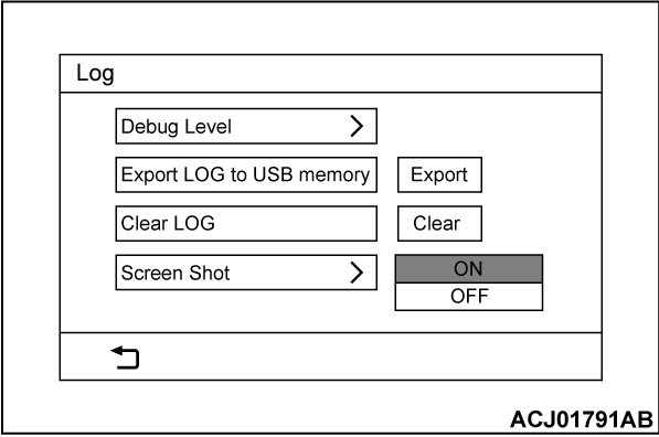
<Screen Shot>
1. Select "Screen Shot" button on "Log" screen.
2. When the sub menu is displayed, select ON/OFF.
3. Connect the USB flash drive to the USB adapter.
4. Press the "PHONE" button for five seconds. A screen shot will be saved in the USB flash drive.
| note | The screen shot will be saved only in the USB adapter on one side. If the screen shot cannot be saved, connect the USB flash drive to the USB adapter on the other side. |
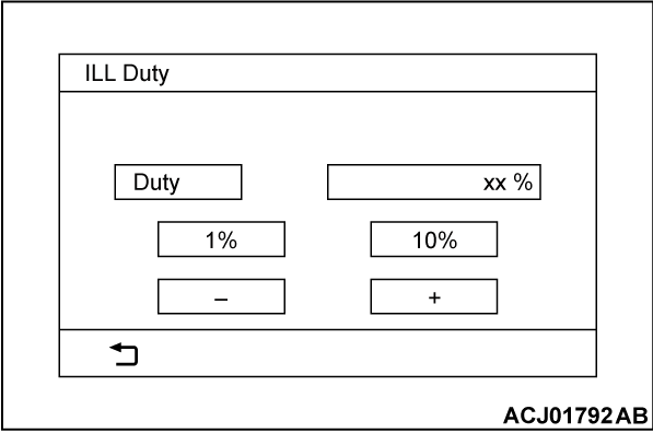
ILL Duty
Displays the brightness information of the multivision display illumination.
1. Select "ILL Duty" button on "Dealer Mode" screen.
2. The information you set on "ILL Duty" screen will be displayed.
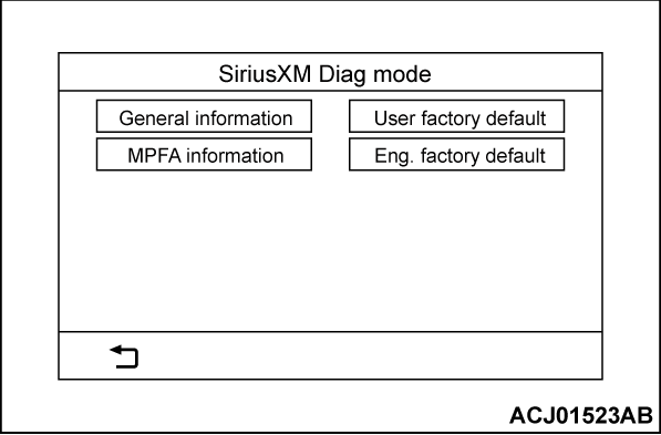
SiriusXM Diag mode
Displays the SiriusXM information.
1. Select "SiriusXM Diag mode" button on "Dealer Mode" screen.
2. The following items will be the "SiriusXM Diag mode" screen.
- General information
- MPFA information
- User factory default
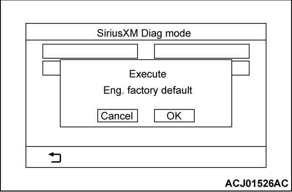
- Eng. factory default
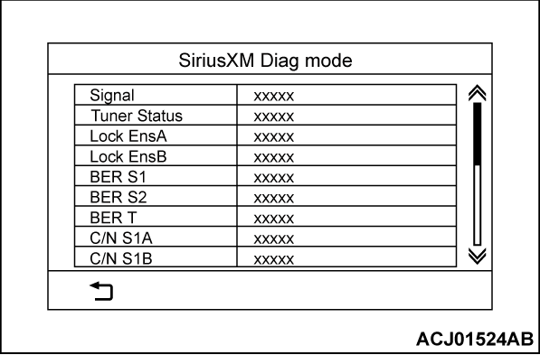
<General information>
1. Select "General information" button on "SiriusXM Diag mode" screen.
2. The information will be displayed.
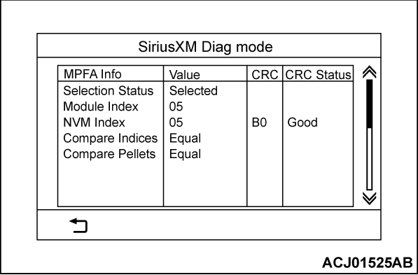
<MPFA information>
1. Select "MPFA information" button on "SiriusXM Diag mode" screen.
2. The information will be displayed.
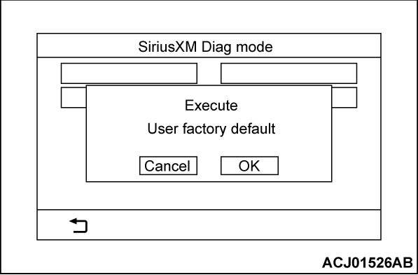
<User factory default>
1. Select "User factory default" button on "SiriusXM Diag mode" screen.
2. A message window is displayed. Press the "OK" button to reset the user factory default. After the reset is complete, the multivision display will be restarted.
![[Previous]](../../../buttons/fprev.png)
![[Next]](../../../buttons/fnext.png)
