DTC B1403: Driver's Air bag Module (1st squib) System (Shorted to Squib Circuit Power Supply)
DTC B1483: Driver's Air bag Module (2nd squib) System (Shorted to Squib Circuit Power Supply
DTC B1483: Driver's Air bag Module (2nd squib) System (Shorted to Squib Circuit Power Supply
| caution |
|
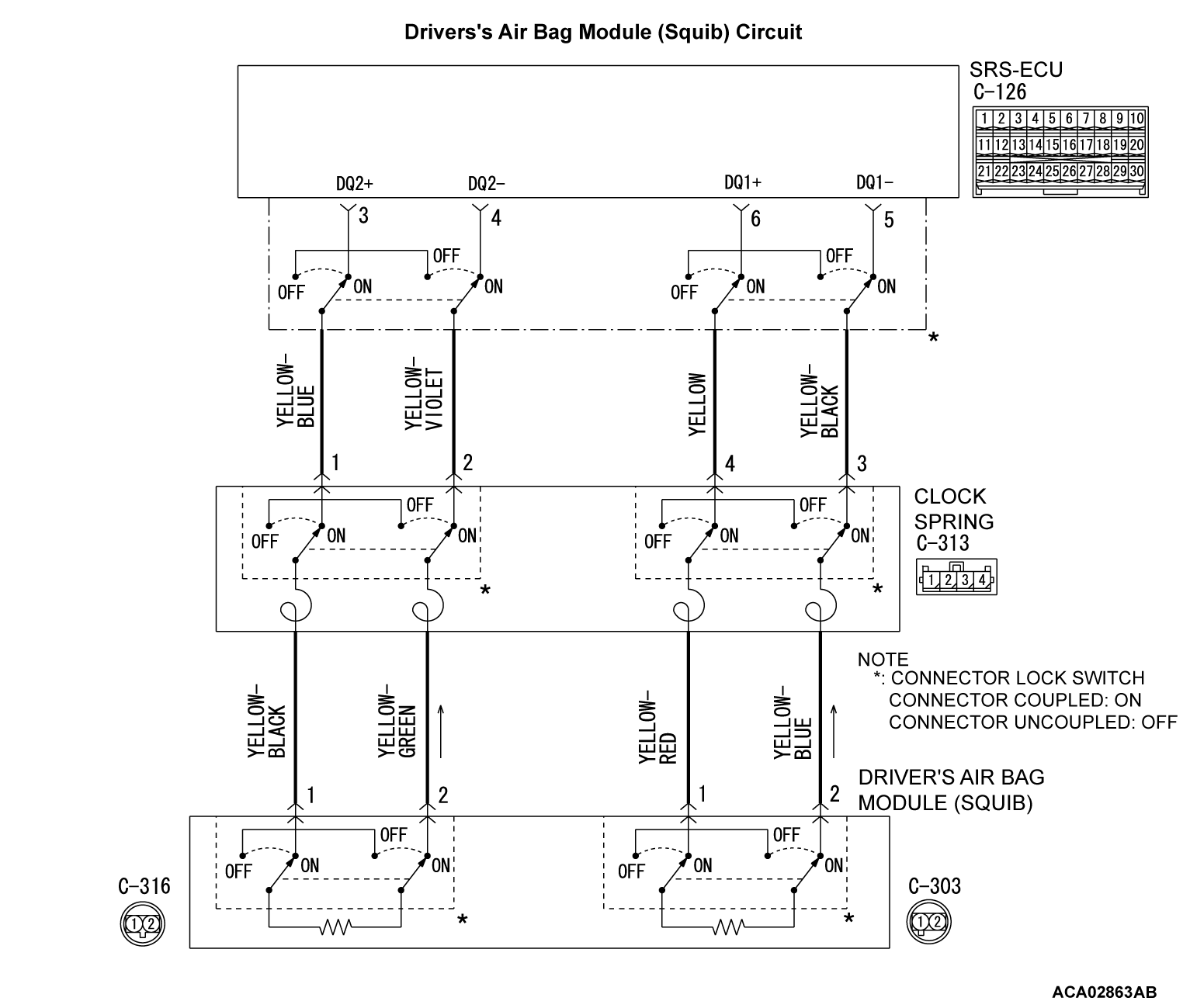
CIRCUIT OPERATION
- The SRS-ECU judges how severe a collision is by detecting signals from the front impact sensors and the front air bag analog G-sensor. If the impact is over a predetermined level, the SRS-ECU sends an ignition signal. At this time, if the front air bag safing G-sensor is on, the SRS air bag will inflate.
- The ignition signal is input to the air bag module via the clock spring to inflate the air bag.
DTC SET CONDITIONS
This DTC is stored if there is abnormal resistance between the input terminals of the driver's air bag module (squib).
TROUBLESHOOTING HINTS
- Malfunction of the clock spring
- Damaged harness wires and connectors
- Short to the power supply in the driver's air bag module (squib) harness
- Malfunction of the SRS-ECU
DIAGNOSIS
STEP 1. Using scan tool MB991958, diagnose the CAN bus line.
(1)
| caution | To prevent damage to scan tool MB991958, always turn the ignition switch to the "LOCK" (OFF) position before connecting or disconnecting scan tool MB991958. |
(2) Turn the ignition switch to the "ON" position.
(3) Diagnose the CAN bus line.
(4) Turn the ignition switch to the "LOCK" (OFF) position.
Is the CAN bus line found to be normal?
STEP 2. Recheck for diagnostic trouble code.
Check again if the DTC is stored.
(1) Erase the DTC.
(2) Turn the ignition switch to the "ON" position.
(3) Check if the DTC is stored.
(4) Turn the ignition switch to the "LOCK" (OFF) position.
Is the DTC stored?
STEP 3. Check the driver's air bag module.
(1) Disconnect the negative battery terminal.
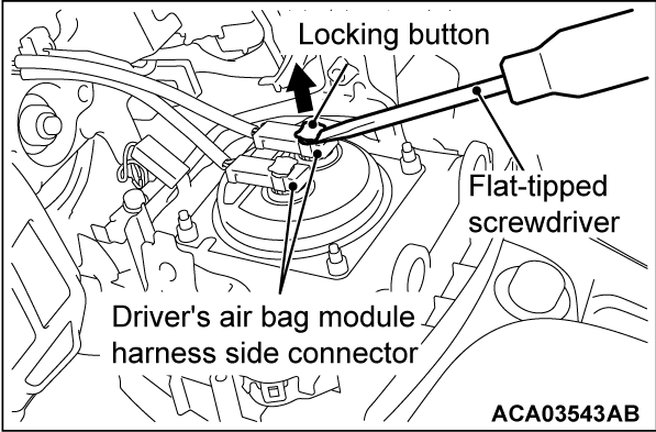
(2) Use the flat-tipped screwdriver to pull out the locking button of wiring harness side connector, and release the lock.
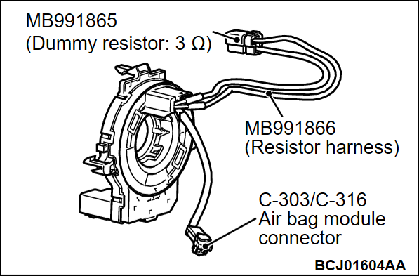
(3) Connect special tool MB991865 to special tool MB991866.
(4)
Insert the resistor harness probe (special tool) as shown.
| caution | Do not insert a probe into the terminal from its front side directly, as the connector contact pressure may be weakened. |
(5) Connect the negative battery terminal.
(6)
| caution | Always DTC B1481 is stored when checking DTC B1403. This is because the second side terminal is isolated when checking it. DTC B1481 is stored but this is not a fault. In addition, always DTC B1401 is stored when checking DTC B1483 because the first side terminal is isolated. |
Erase the diagnostic trouble code memory, and check the diagnostic trouble code.
Is the checked DTC stored?
STEP 4. Check the clock spring.
(1) Disconnect the negative battery terminal.
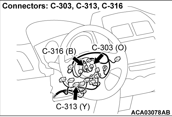
(2) Disconnect the clock spring connector C-313.
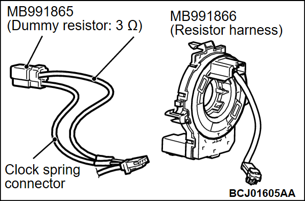
(3) Connect special tool MB991865 to special tool MB991866.
(4)
| caution | Do not insert a test probe into the terminal from its front side directly, as the connector contact pressure may be weakened. |
Insert the resistor harness probe from the back of C-313 harness side connector terminals Nos. 3 and 4 <1st squib> or terminal No. 2 and 1 <2nd squib>).
(5) Connect the negative battery terminal.
(6)
| caution | Always DTC B1B06 is stored when checking DTC B1403. This is because the second side terminal is isolated when checking it. DTC B1B06 is stored but this is not a fault. In addition, always DTC B1B02 is stored when checking DTC B1483 because the first side terminal is isolated. |
Erase the diagnostic trouble code memory, and check the diagnostic trouble code.
Is the checked DTC stored?
STEP 5. Check the driver’s air bag module circuit. Measure the voltage at the SRS-ECU connector C-126.
(1) Disconnect the negative battery terminal.
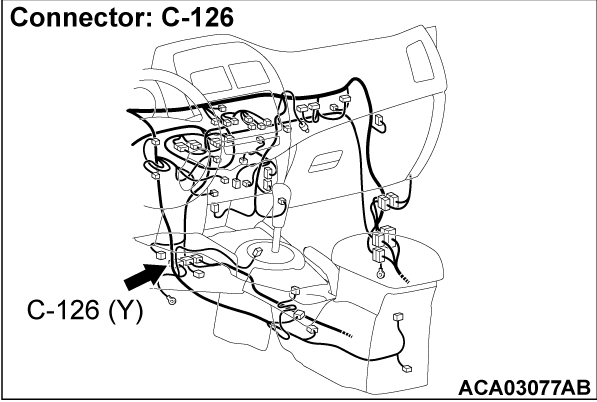
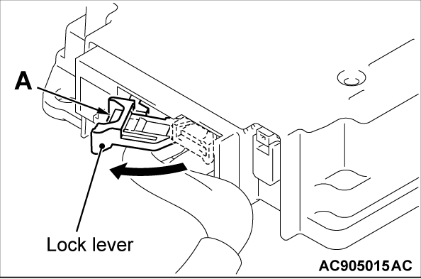
(2) While pushing the part "A" indicated in the figure of the harness side connector, turn the lock lever to the direction of the arrow to release the lock lever, and disconnect the C-126 SRS-ECU connector.
(3)
| danger | To prevent the air bag from deploying unintentionally, disconnect the clock spring connector C-313 to short the squib circuit. |
Disconnect the clock spring connector C-313.
(4)
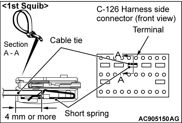
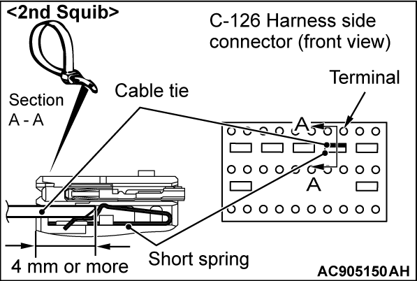
| caution | Insert an insulator such as a cable tie to a depth of 4mm (0.16 inch) or more, otherwise the short spring will not be released. |
Insert a cable tie [3 mm (0.12 inch) wide, 0.5 mm (0.02 inch) thick] between terminals 5, 6 <1st squib> or 3, 4 <2nd squib> and the short spring to release the short spring.
(5) Connect the negative battery terminal.
(6) Ignition switch: ON.
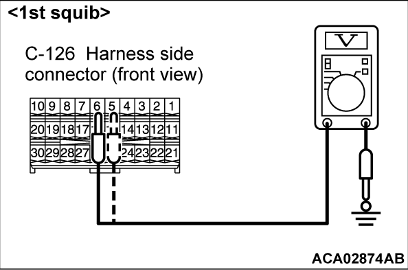
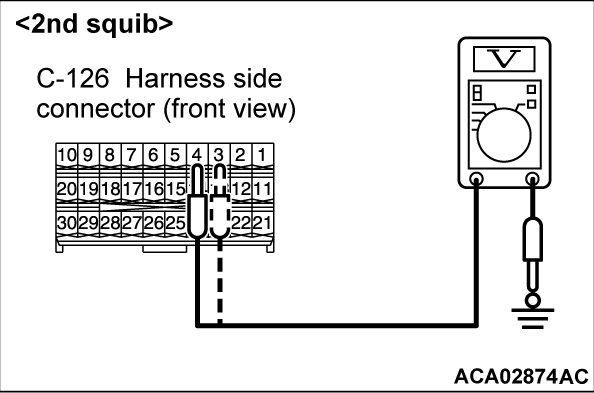
(7) Measure the voltage between C-126 harness side connector terminals 5 and 6 <1st squib> or 3 and 4 <2nd squib> and body ground.Voltage should measure 1 volt or less.
Is the measured voltage within the specified range?
STEP 6. Check the harness for short circuit to power supply between the following connector.
- SRS-ECU connector C-126 (terminal No.5 and 6) and clock spring connector C-313 (terminal No.3 and 4) <1st squib>.
- SRS-ECU connector C-126 (terminal No.3 and 4) and clock spring connector C-313 (terminal No.1 and 2) <2nd squib>.
Is the check result normal?
STEP 7. Recheck for diagnostic trouble code.
Check again if the DTC is stored. The procedure is complete.
(1) Erase the DTC.
(2) Turn the ignition switch to the "ON" position.
(3) Check if the DTC is stored.
(4) Turn the ignition switch to the "LOCK" (OFF) position.
Is DTC B1403 <1st squib> or B1483 <2nd squib> stored?
 The procedure is complete.
![[Previous]](../../../buttons/fprev.png)
![[Next]](../../../buttons/fnext.png)
