GENERAL INFORMATION
| danger | The SRS-ECU adopts the rollover specification that the curtain airbag and seat belt pre-tensioner operate at the occurrence of rollover. Therefore, do not tilt the vehicle to the right and left with the IG ON or tilt the SRS-ECU to the right and left with the IG ON and the harness installed. |
| warning | Improper service could result in serious injury of the service personnel or the passenger. |
The SRS is designed to supplement the front seat belts. It reduces injury to the driver(s) and the front passenger(s) by deploying air bag(s) in case of a frontal collision. In addition, the side-airbag and curtain air bag inflate upon a side collision to reduce the risk of passenger injuries.
The SRS front air bags from an advanced air bag system together with sensors at the vehicle and sensors attached to front seats.
Side-airbag systems in the front seats are activated when side impacts exceed a criteria to protect the occupants’ upper bodies.
The curtain airbag system operates together with the side-airbag to protect the heads of passengers in the front and second seats.
The seat belts with pre-tensioner work simultaneously with the SRS. The seat belt incorporating the pre-tensioner automatically winds the seat belt upon front impact to reduce forward shifting of the driver’s and passenger’s. The seat belt use status is used to control the activation and deactivation of the pre-tensioner.
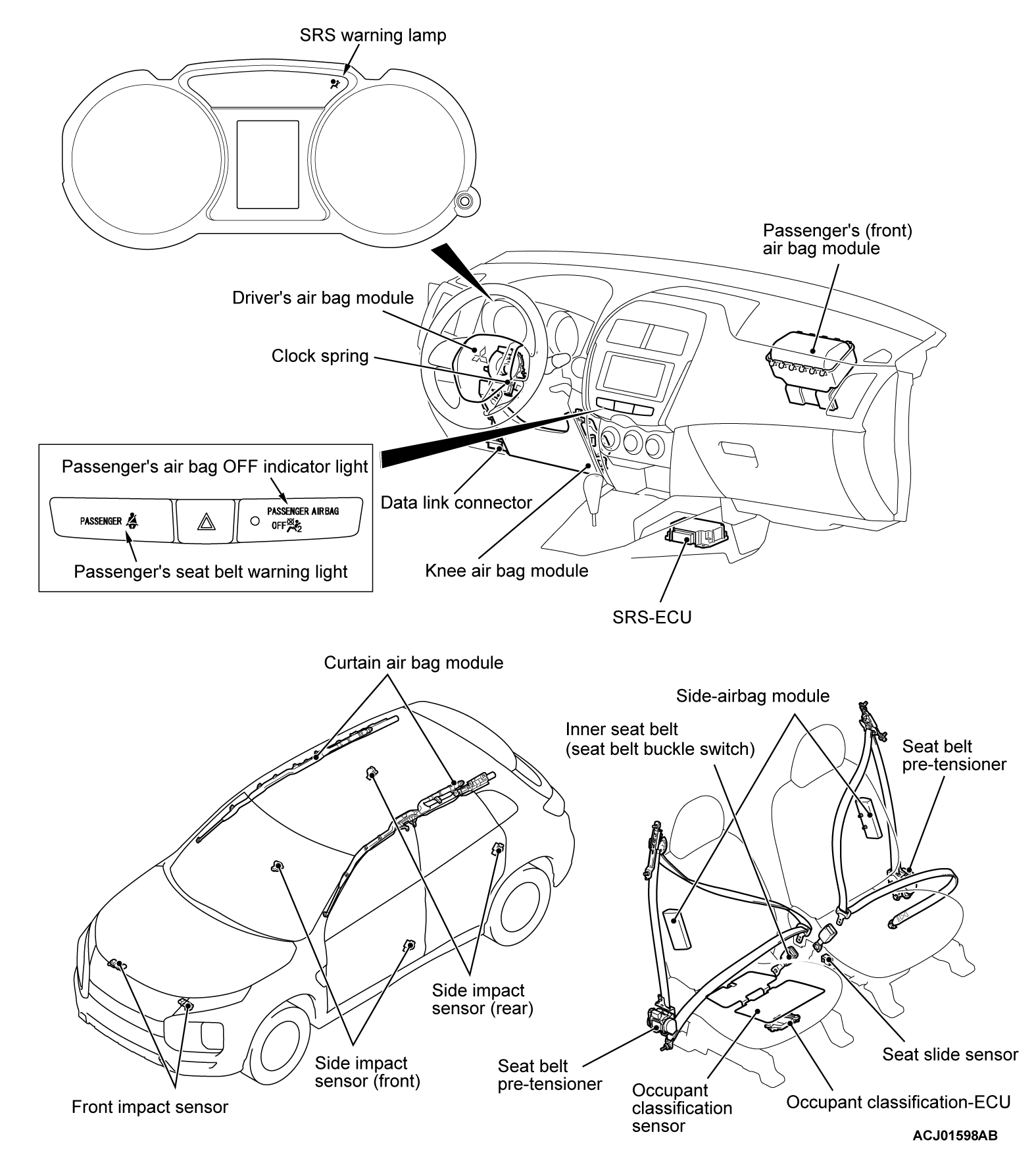
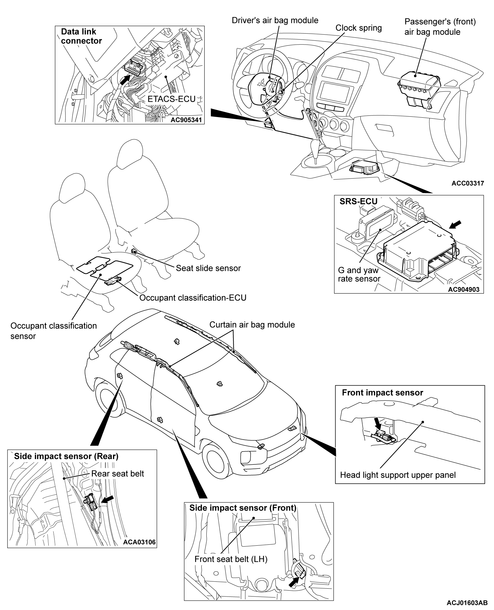
The SRS consists of air bag modules, SRS air bag control unit (SRS-ECU), front impact sensors, side impact sensors, SRS warning light, passenger’s air bag OFF indicator light, passenger’s seat belt warning light, clock spring, seat belt pre-tensioner, seat belt switch, seat slide sensor, weight sensor and occupant classification-ECU. Air bag modules are located in the center of the steering wheel and above the glove box. Knee air bag is installed under the column cover. Side-airbags are located inside the front seatback assemblies. The curtain air bag module consists of an air bag, an inflator, and the fixing gear relating to those parts, and is installed in the roof side sections (from the driver's and the passenger's front pillars to the rear pillars). Each air bag consists of a folded air bag and an inflator unit. The SRS-ECU placed on the forefront of the floor monitors the system and has a front air bag safing G-sensor, front air bag analog G-sensor and a side-airbag safing G-sensor. The front impact sensor is assembled in the front end upper bar to monitor impact in case of front impact. The side impact sensors inside the center pillars and the rear quarter panel monitor the shock incurred by the sides of the vehicle. The SRS warning light on the combination meter indicates the operational status of the SRS. The clock spring is installed in the steering column. The seat belt pre-tensioner is built into the driver's and passenger's front seat belt retractor. The seat slide sensor is installed at the seat adjuster section of the driver seat in order to detect the driver seat slide position. The weight sensor is installed underneath a rail of the passenger seat to detect the load on the seat. The passenger’s air bag OFF indicator light is installed to the lower left of the center panel, and illuminates when the passenger seat airbag is inactive. The passenger’s seat belt warning light is installed to the lower right of the center panel, and illuminates when the passenger is not wearing the seat belt. The seat belt switch detects whether the seat belt is used.
Only authorized service personnel should do work on or around the SRS components. Those service personnel should read this manual carefully before starting any such work.
ON-BOARD DIAGNOSTIC/SRS WARNING LIGHT FUNCTION
The SRS-ECU monitors the SRS system and stores data concerning any detected faults in the system. When the ignition switch is in "ON" position, the SRS warning light, passenger’s air bag OFF indicator light and passenger’s seat belt warning light should illuminate for about seven seconds and then turn "OFF." That indicates that the SRS system is in operational order. If the SRS warning light does any of the following, the immediate inspection by an authorized dealer is needed:
1. The SRS warning light does not illuminate as described above.
2. The SRS warning light stays on for more than seven seconds.
3. The SRS warning light illuminates while driving.
If a vehicle's SRS warning light is in any of these three conditions, the SRS system must be inspected, diagnosed and serviced in accordance with this manual.
CONSTRUCTION DIAGRAM
| note | This construction diagram shows the general view of the SRS components. For details, refer to "Schematic ( ), "Configuration Diagrams ( ), "Configuration Diagrams ( ), " and "Circuit Diagram ( ), " and "Circuit Diagram ( )". )". |
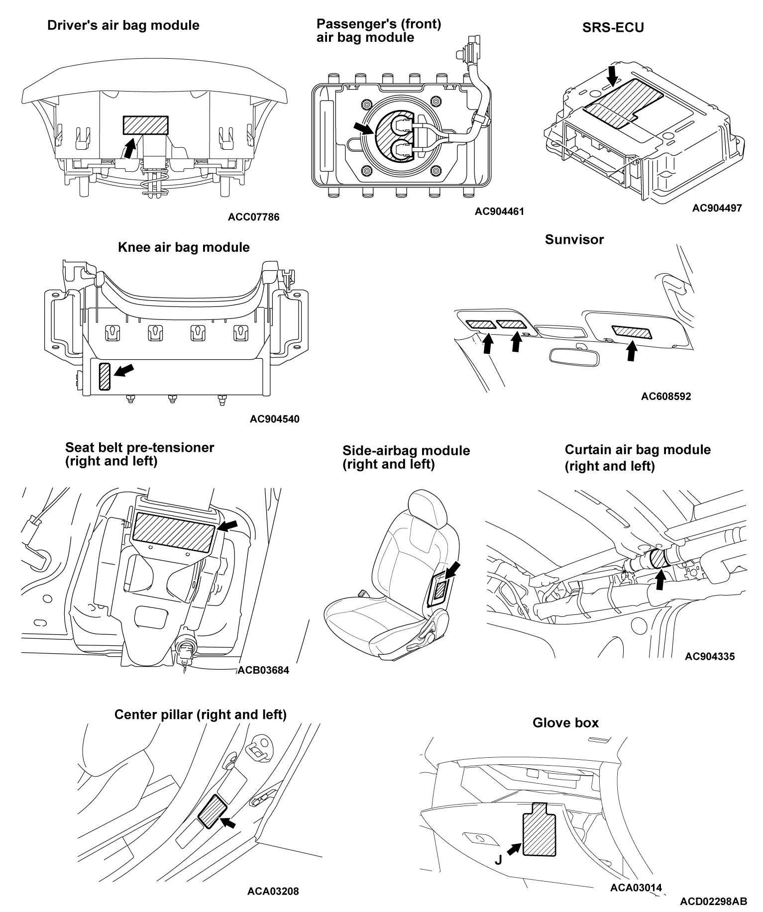
WARNING/CAUTION LABELS
The labels indicating the precautions for handling and maintenance of SRS air bags and seat belt with pre-tensioner are attached to the locations shown in the figure. If the label is damaged or is dirty, replace with the new label.SRS AIR BAG SPECIAL CONNECTOR
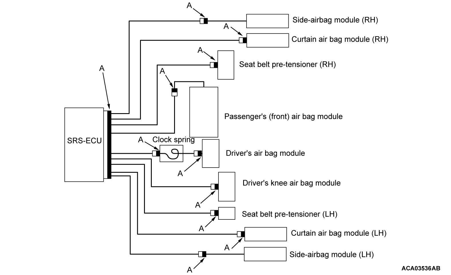
To enhance the system reliability, a connector short circuiting mechanism is integrated in the SRS-ECU connector, air bag module connectors, clock spring connector, pre-tensioner connectors, and intermediate connector between curtain air bag module and SRS-ECU (black connector "A" shown in the figure).
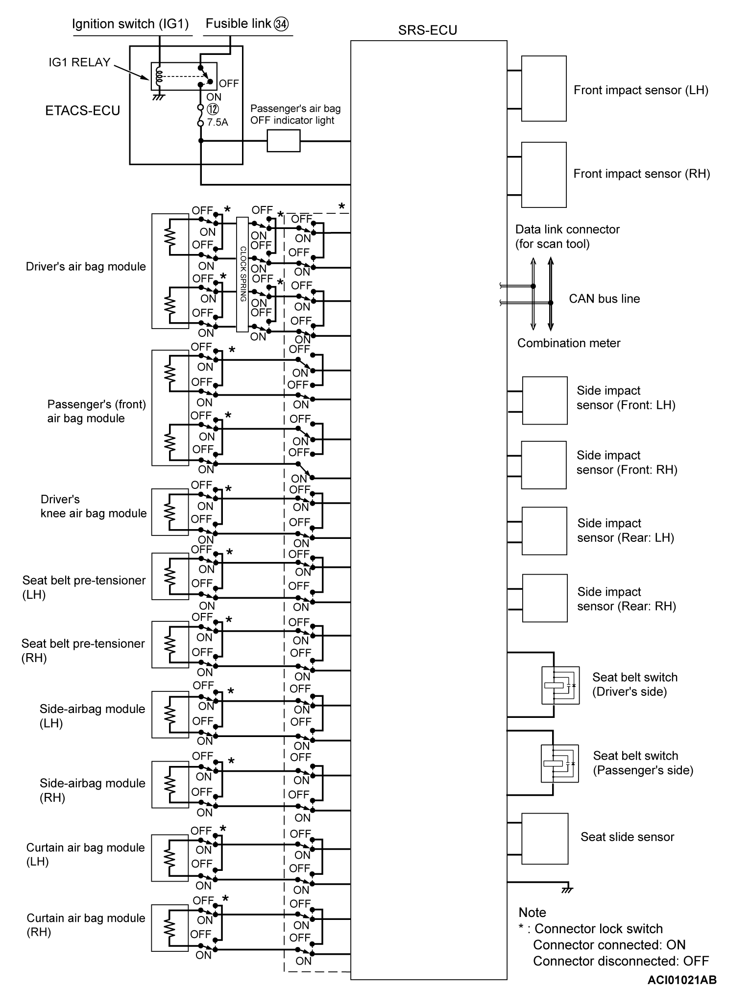
SQUIB CIRCUIT CONNECTOR LOCK SWITCH
This mechanism prevents the improper deployment of air bag module because of the current application to the squib due to the static electricity when connectors between SRS-ECU and air bag modules (squibs) are disconnected. When the connector is disconnected, the short spring short circuits the power supply side terminal and ground side terminal of squibs, and prevents the static electricity from generating the potential difference. This connector mechanism is adopted for the following connectors.
- SRS-ECU connector
- Connector between the clock spring and body-side wiring harness
- Each air bag module connector
- Each pre-tensioner connector
- Intermediate connector between curtain air bag module and SRS-ECU
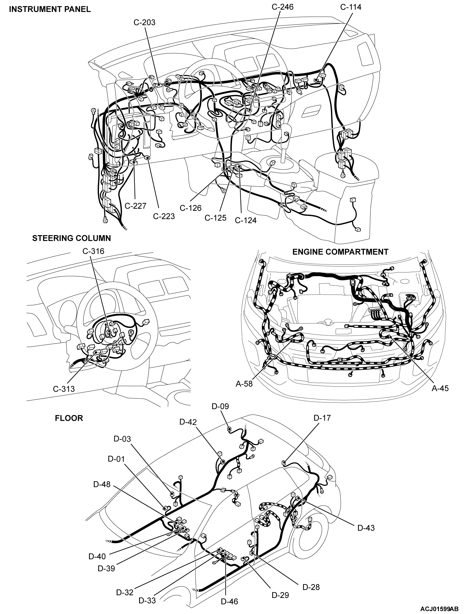
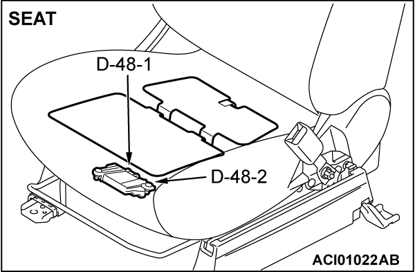
CONFIGURATION DIAGRAMS
|
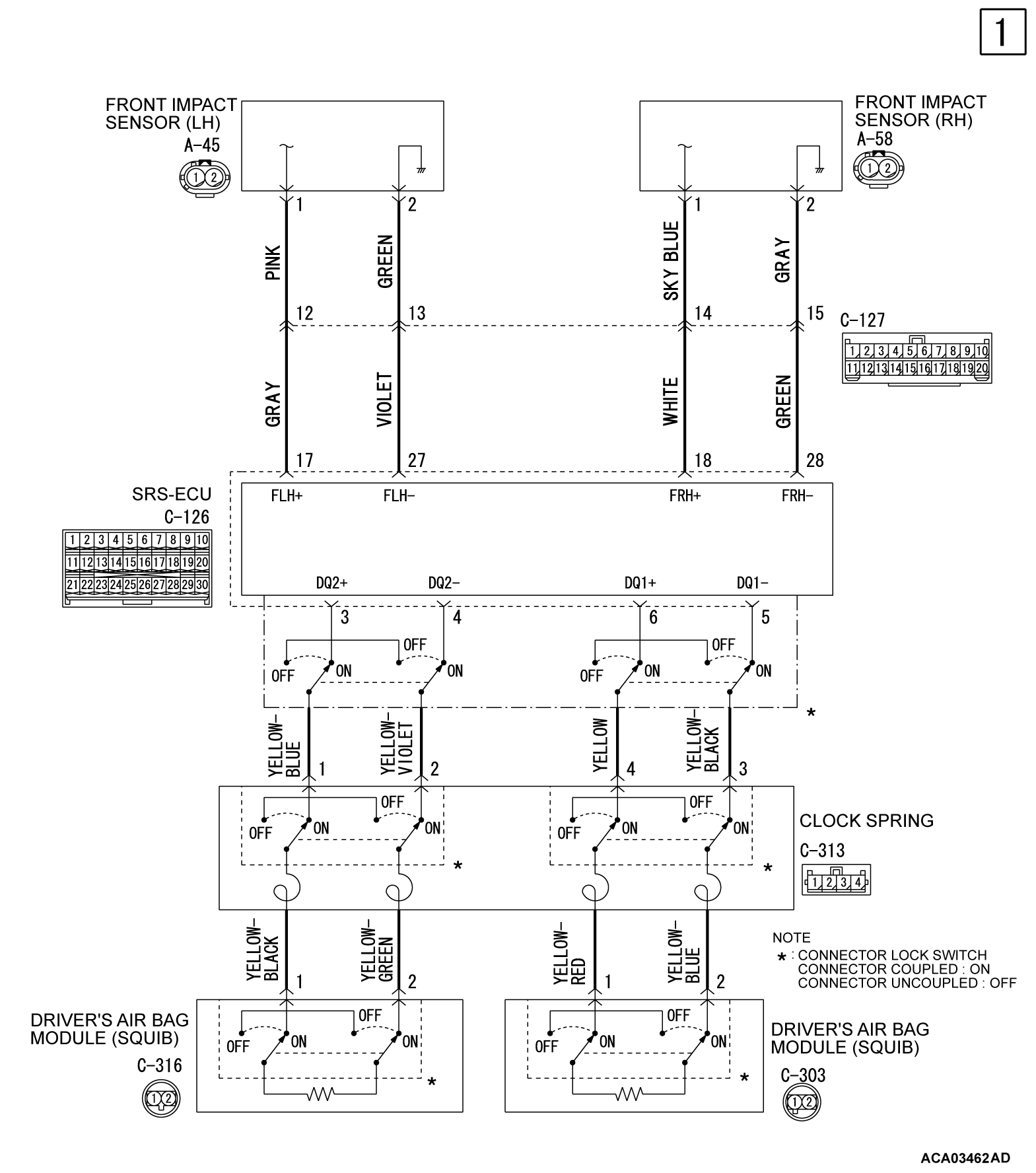
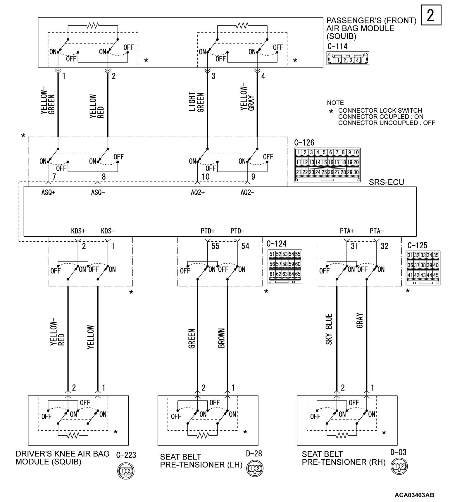
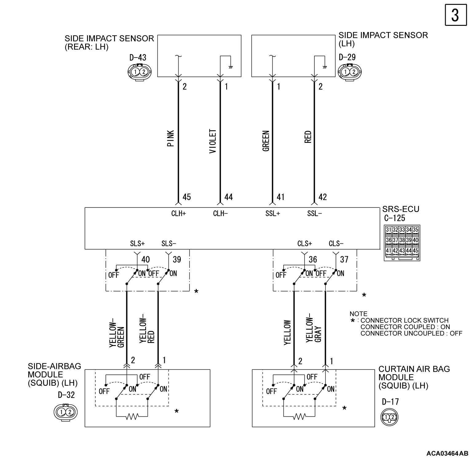
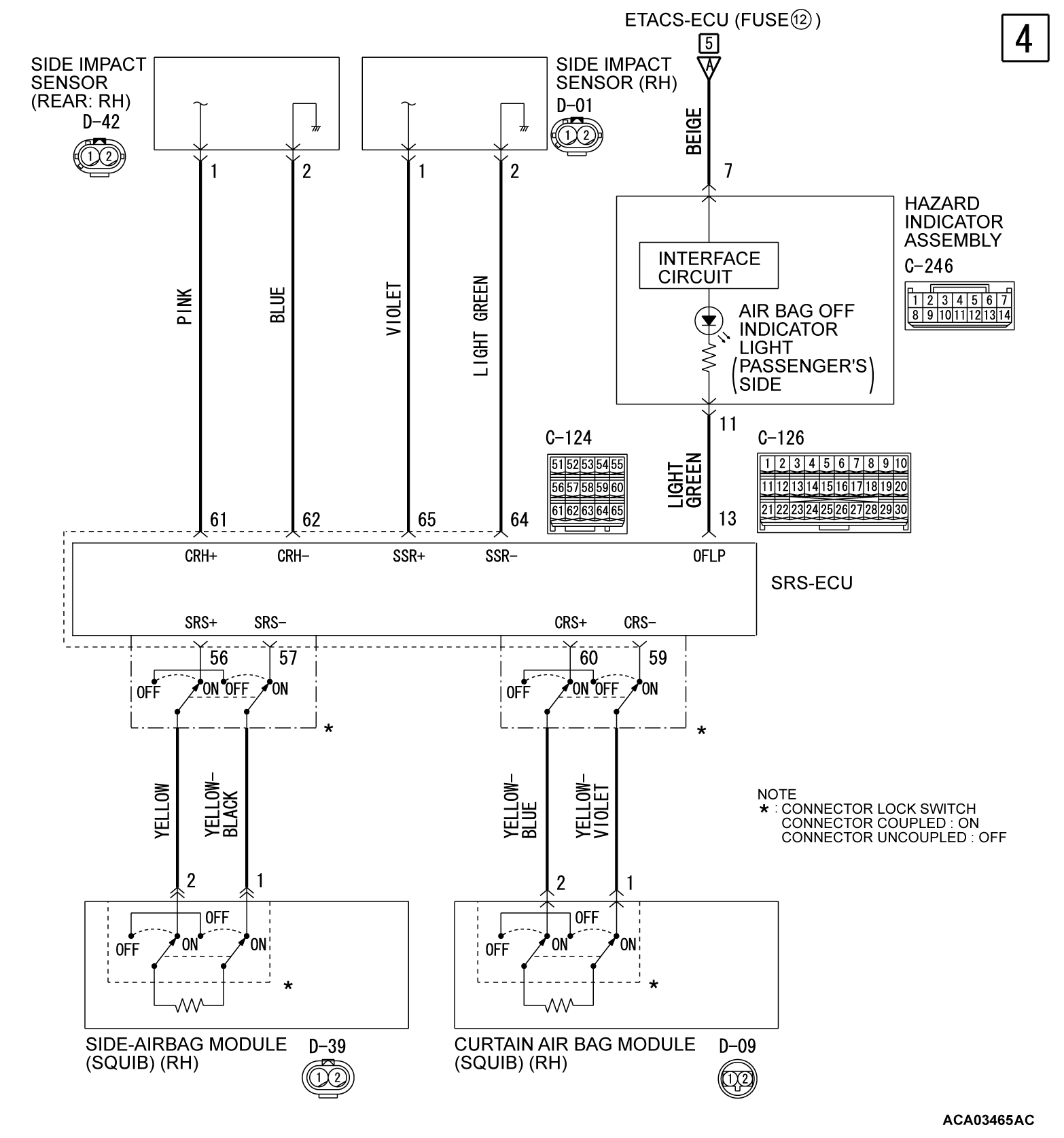
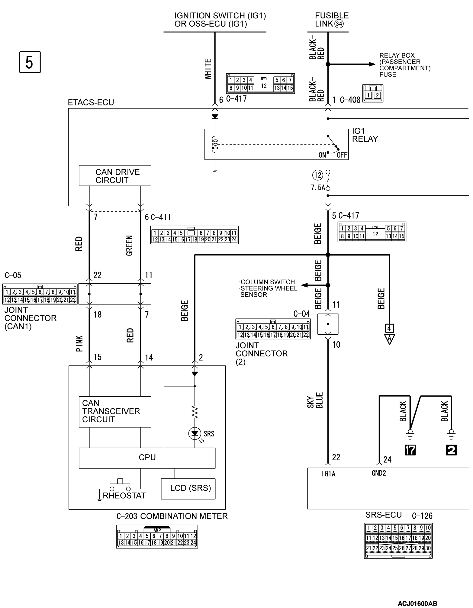
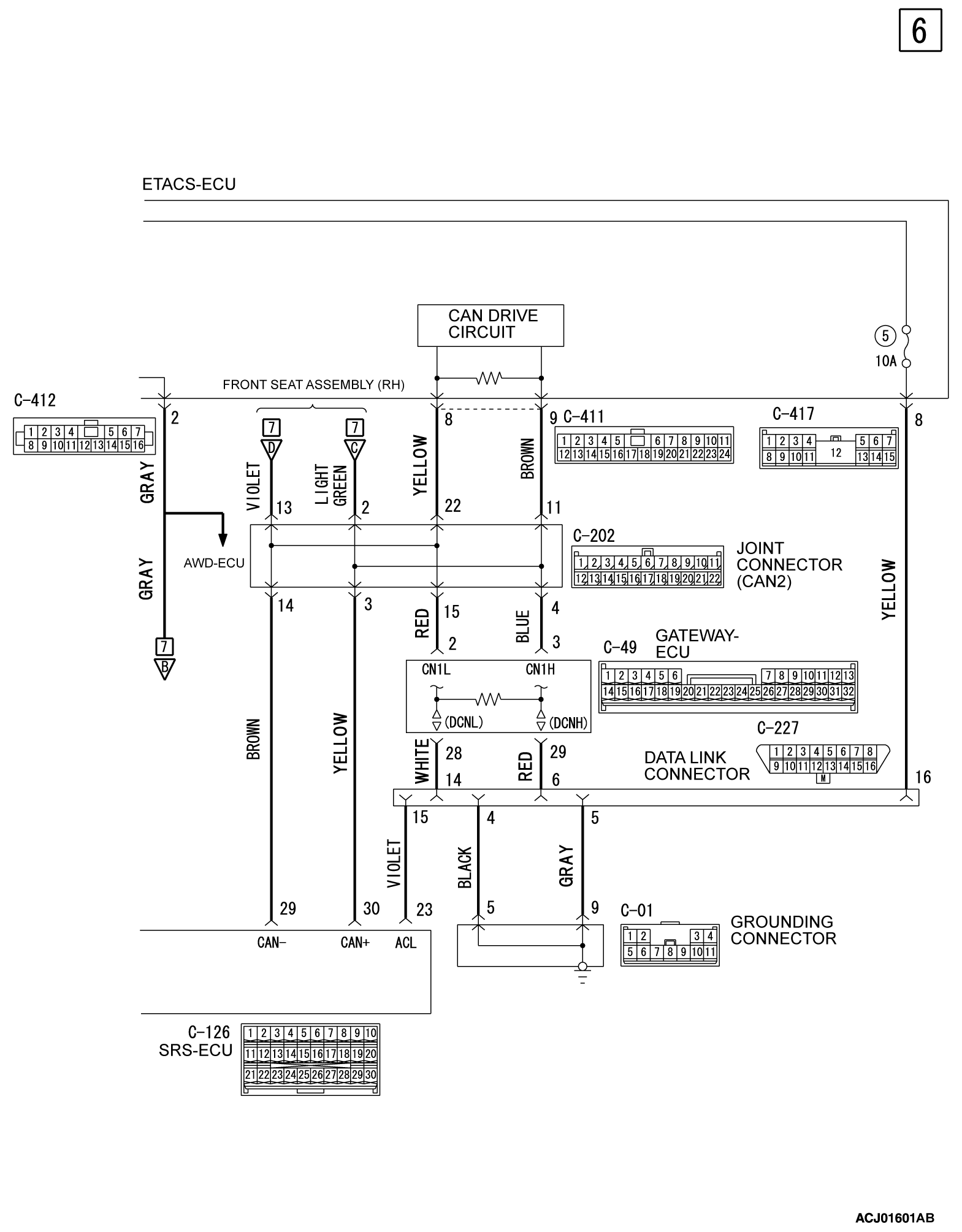
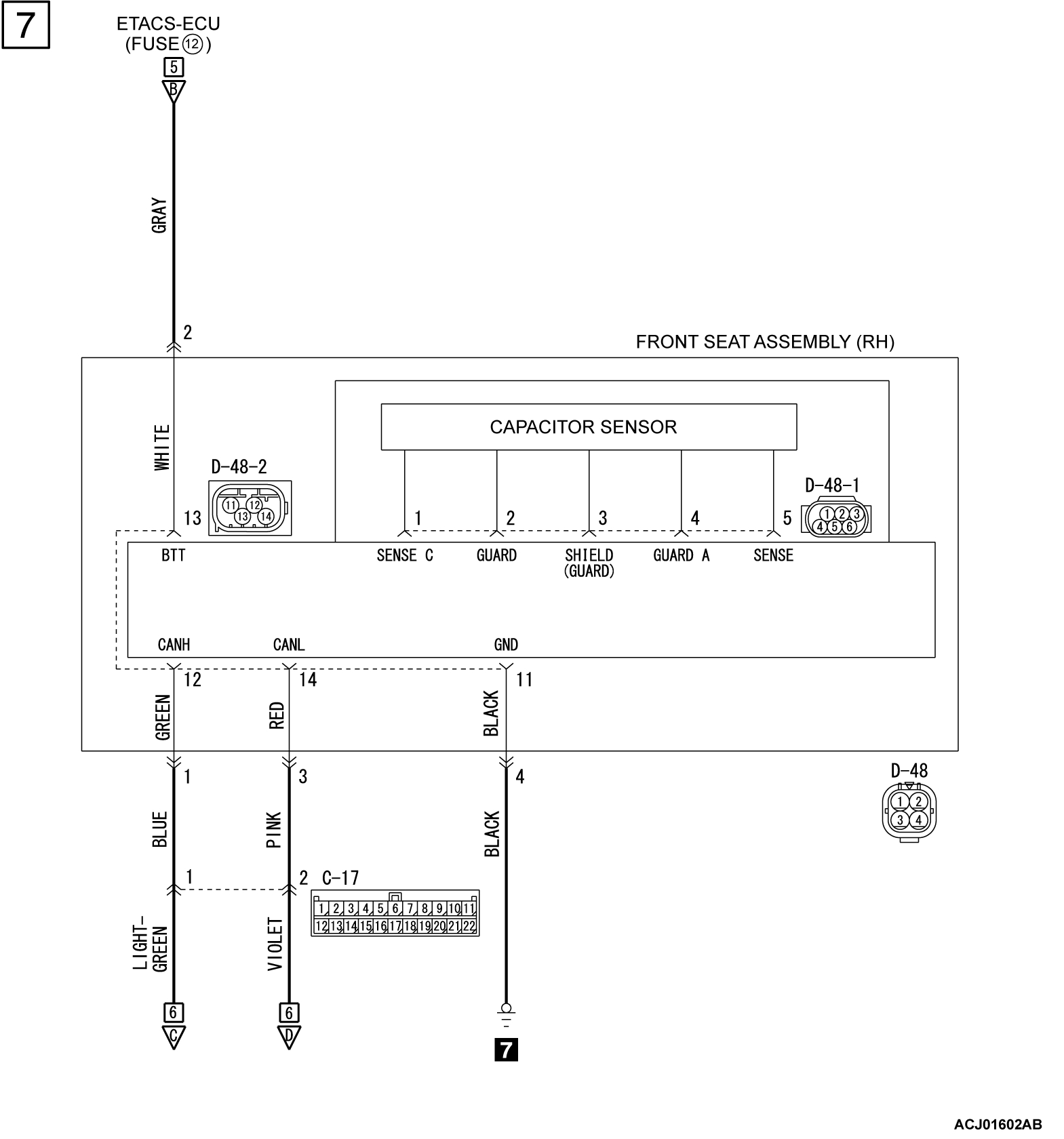
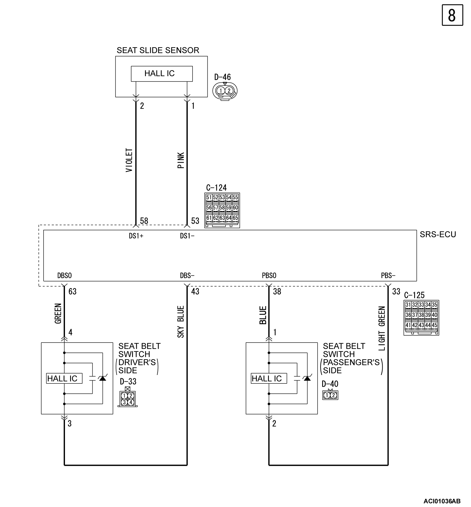
CIRCUIT DIAGRAM
| caution | Improper services cause the system to be inoperative. Do not disassemble or tamper with the SRS components to prevent the serious injury. |
![[Previous]](../../../buttons/fprev.png)
![[Next]](../../../buttons/fnext.png)

