Inspection Procedure 14: Steering wheel sensor power supply circuit system
OPERATION
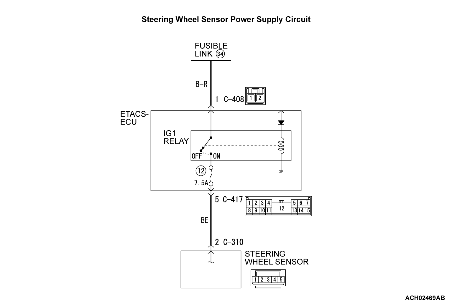
- Steering wheel sensor contains the power supply circuit (terminal No.2) for Steering wheel sensor. The power is supplied from the ETACS-ECU (terminal No.5). The power is supplied from the fusible link No.34 through the multi-purpose fuse No.12.
- When malfunction occurs in Steering wheel sensor power supply, the communication with scan tool becomes unavailable.
PROBABLE CAUSES
- Damaged wiring harness and connectors
- Fuse and fusible link malfunction
- Improper tightening of battery terminal
- Battery failure
- Charging system failed
- Steering wheel sensor malfunction
DIAGNOSIS
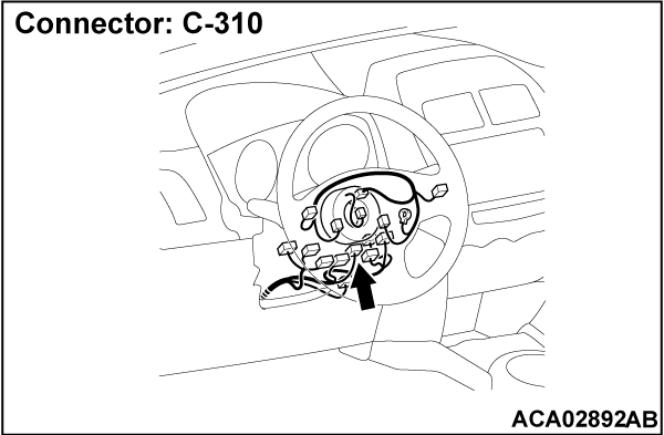
STEP 1. Connector check: C-310 steering wheel sensor connector
STEP 2. Resistance measurement at C-310 steering wheel sensor connector.
(1) Disconnect C-310 steering wheel sensor connector and measure the resistance available at the wiring harness side of the connector.
(2) Check for continuity between C-310 steering wheel sensor connector terminal No.5 and body ground.
OK: Continuity exists (2 Ω or less)
Is the check result normal?
STEP 3. Check the wiring harness between C-310 steering wheel sensor connector terminal No.5 and the body ground.
- Check the ground wires for open circuit.
Is the check result normal?
 If a trouble is solved, it is determined that there is an intermittent malfunction such as poor engaged connector(s) or open circuit (Refer to GROUP 00 - How to use Troubleshooting/How to Cope with Intermittent Malfunctions
  ).
). Repair the wiring harness.
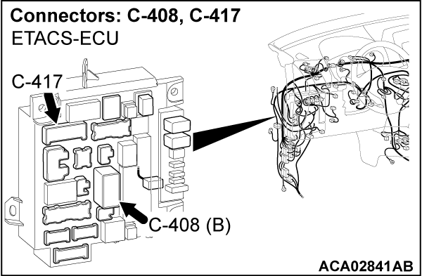
STEP 4. Connector check: C-408 ETACS-ECU connector, C-417 ETACS-ECU connector
STEP 5. Voltage measurement at C-408 ETACS-ECU connector
(1) Disconnect C-306 ETACS-ECU connector and measure the voltage available at the wiring harness side of the connector.
(2) Measure the voltage between C-408 ETACS-ECU connector terminal No.1 and body ground.
OK: Approximately system voltage
Is the check result normal?
STEP 6. Check the wiring harness between fusible link No. 34 and C-408 ETACS-ECU connector terminal No.1.
- Check the power supply lines (battery power supply) for open circuit and short circuit.
Is the check result normal?
 If a trouble is solved, it is determined that there is an intermittent malfunction such as poor engaged connector(s) or open circuit (Refer to GROUP 00 - How to use Troubleshooting/How to Cope with Intermittent Malfunctions
  ).
). Repair the wiring harness.
STEP 7. Measure the voltage at the C-310 steering wheel sensor connector.
(1) Disconnect C-310 steering wheel sensor connector and measure the voltage at the wiring harness side of the connector.
(2) Turn the ignition switch to the ON position.
(3) Measure the voltage between the terminal No.2 and the body ground.
OK: Approximately system voltage
Is the check result normal?
STEP 8. Check the fuse No.12.
Visually check for open circuit in fuse No.12. The short circuit may be present in the power supply circuit. Check the wiring harness between the C-310 steering wheel sensor connector terminal No.2 and the C-417 ETACS-ECU connector terminal No.5, and repair if necessary. And then replace the fuse No.12.
Is the check result normal?
 The short circuit may be present in the power supply circuit. Check the wiring harness between the C-310 steering wheel sensor connector terminal No.2 and the C-417 ETACS-ECU connector terminal No.5, and repair if necessary. And then replace the fuse No.12.
STEP 9. Check the wiring harness between C-310 steering wheel sensor connector terminal No.2 and C-417 ETACS-ECU connector terminal No.5.
- Check the power supply lines (battery power supply) for open circuit.
Is the check result normal?
 Repair the wiring harness between the C-310 steering wheel sensor connector terminal No.2 and the C-417 ETACS-ECU connector terminal No.5.
STEP 10. Using scan tool MB991958, check the ETACS system data list
Check the input signal of IG1 relay.
 Replace the steering wheel sensor.
- Turn the ignition switch to the ON position.
|
OK: Normal condition is displayed.
Is the check result normal?
 Replace the steering wheel sensor.
![[Previous]](../../../buttons/fprev.png)
![[Next]](../../../buttons/fnext.png)


