[Previous][Next]
REMOVAL AND INSTALLATION
 
 
MASTER CYLINDER AND BRAKE BOOSTER
caution
  • The master cylinder assembly cannot be disassembled. Perform the operation below with care to prevent falling-off of the piston, because structurally the piston comes off easily.
    • Do not remove the cover mounted on the master cylinder assembly (service parts) until the installation work.
    • During the master cylinder assembly operation, handle it with the piston facing upwards.
    • To remove the master cylinder assembly from the brake booster assembly, depress the brake pedal several times to release the negative pressure in the brake booster assembly before removal.
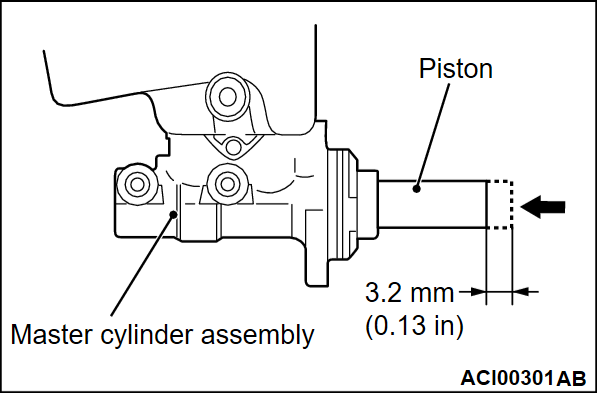
  • If the piston moves 3.2 mm (0.13 inch) or more by pushing it, replace the master cylinder assembly with a new one.
  • Do not damage the piston by impact, pinching, and so on.
  • Do not touch the piston directly by hand. To handle it, hold the body section of the master cylinder assembly.
  • Do not allow foreign matters to adhere to the piston. If foreign matter adheres to it, remove the foreign matter carefully so that the piston does not come off, using a new dry rag. Do not use water or detergent.
Pre-removal operation
  • Brake Fluid Draining
  • Air Cleaner Body Removal (Refer to GROUP 15 - Air Cleaner ).
Post-installation operation
  • Air Cleaner Body Installation (Refer to GROUP 15 - Air Cleaner ).
  • Brake Fluid Refilling and Air Bleeding (Refer to ).
  • Brake Pedal Adjustment .
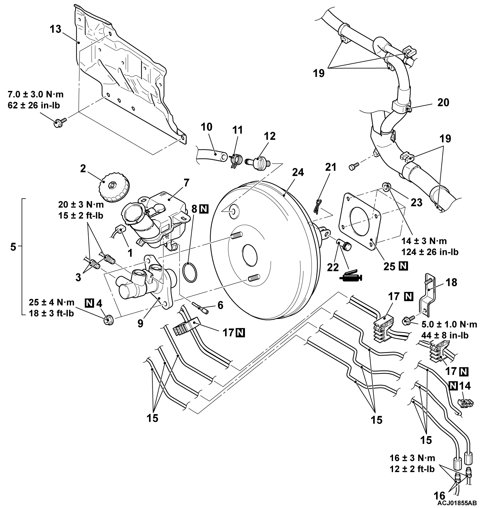
Master cylinder removal steps
1.Brake fluid level switch connector
2.Reservoir cap
3.Brake pipe connection
>>B<<Bleeding of master cylinder assembly (only at installation)
4.Master cylinder mounting nut
5.Reservoir assembly and master cylinder assembly
6.Torx bolt
7.Reservoir assembly
8.O-ring
<<A>>>>D<<9.Master cylinder assembly
>>C<<Push rod depth adjustment <only at installation>
Brake booster removal steps
1.Brake fluid level switch connector
3.Brake pipe connection
>>B<<Bleeding of master cylinder assembly (only at installation)
4.Master cylinder mounting nut
5.Reservoir assembly and master cylinder assembly
>>A<<10.Vacuum hose connection
11.Hose clip
12.Check valve
13.Dash panel heat protector
14.Brake fluid line clip
15.Brake pipe and brake fluid line clip connection
16.Brake pipe connection
17.Brake fluid line clip
18.Brake fluid line bracket
19.Front harness connection
20.Front harness connection
21.Snap pin
22.Pin assembly
23.Brake booster mounting nut
24Brake booster assembly
25.Seal
 
 
REMOVAL SERVICE POINT
 
 
<<A>> MASTER CYLINDER ASSEMBLY REMOVAL
caution
  • The master cylinder assembly cannot be disassembled. Perform the operation with care to prevent the falling off of the piston, because structurally the piston comes off easily.
  • If the piston moves 3.2 mm (0.13 inch) or more by pushing it, replace the master cylinder assembly with a new one.


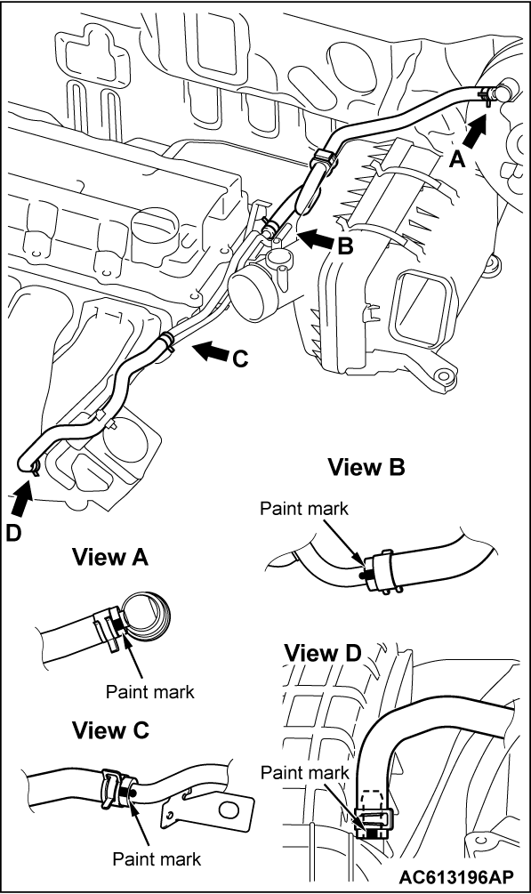
<VACUUM HOSE AND VACUUM PIPE>
Removal steps
>>A<<1.Vacuum hose
2.Hose clip
>>A<<3.Vacuum hose
4.Hose clip
5.Emission vacuum hose connection
6.Vacuum pipe assembly
 
 
INSTALLATION SERVICE POINTS
 
 
>>A<< VACUUM HOSE INSTALLATION
Align the mark as shown in the figure to assemble the vacuum hose.


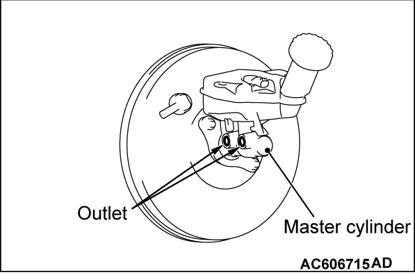
>>B<< BLEEDING OF MASTER CYLINDER ASSEMBLY
When removed the master cylinder assembly, bleed the master cylinder in the following procedure to make bleeding of the brake pipeline easier (When no brake fluid is in the master cylinder).
1. Fill the brake fluid reservoir with the brake fluid.
2. Depress and hold the brake pedal.
3. Another operator closes the master cylinder outlets with his fingers.
4. In this condition, release the brake pedal.
5. Repeat Steps 2 to 4 for 3 or 4 times to fill the master cylinder with the brake fluid.


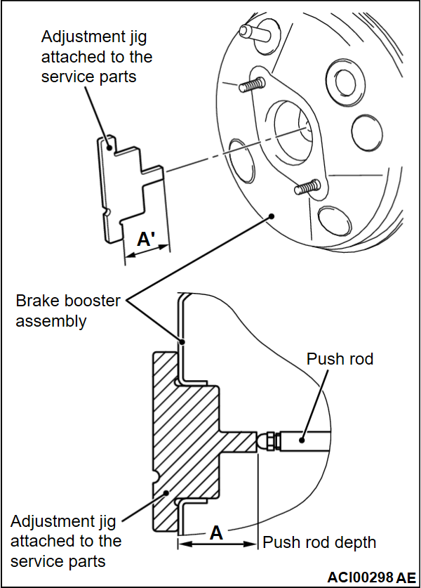
>>C<< PUSH ROD DEPTH ADJUSTMENT
cautionWhen replacing the master cylinder assembly with the new one, the push rod depth must be adjusted using the adjustment jig attached to the service parts. When re-installing the removed master cylinder assembly, the adjustment is not necessary.
1. Check that the push rod depth (A) and the length of the adjustment jig attached to the service parts (A’) are equal (A = A’).
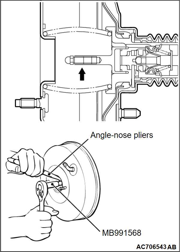
2. When the push rod depth differs from the jig length, use angle nose pliers to fix the push rod at the area indicated with an arrow. Then, use the push rod adjusting socket (special tool: MB991568) to rotate the push rod leading end, and adjust the push rod depth to match with the jig length.
noteIt is recommended to use the angle nose pliers that are commercially available.


>>D<< MASTER CYLINDER ASSEMBLY INSTALLATION
caution
  • The master cylinder assembly cannot be disassembled. Perform the operation with care to prevent the falling off of the piston, because structurally the piston comes off easily.
  • If the piston moves 3.2 mm (0.13 inch) or more by pushing it, replace the master cylinder assembly with a new one.