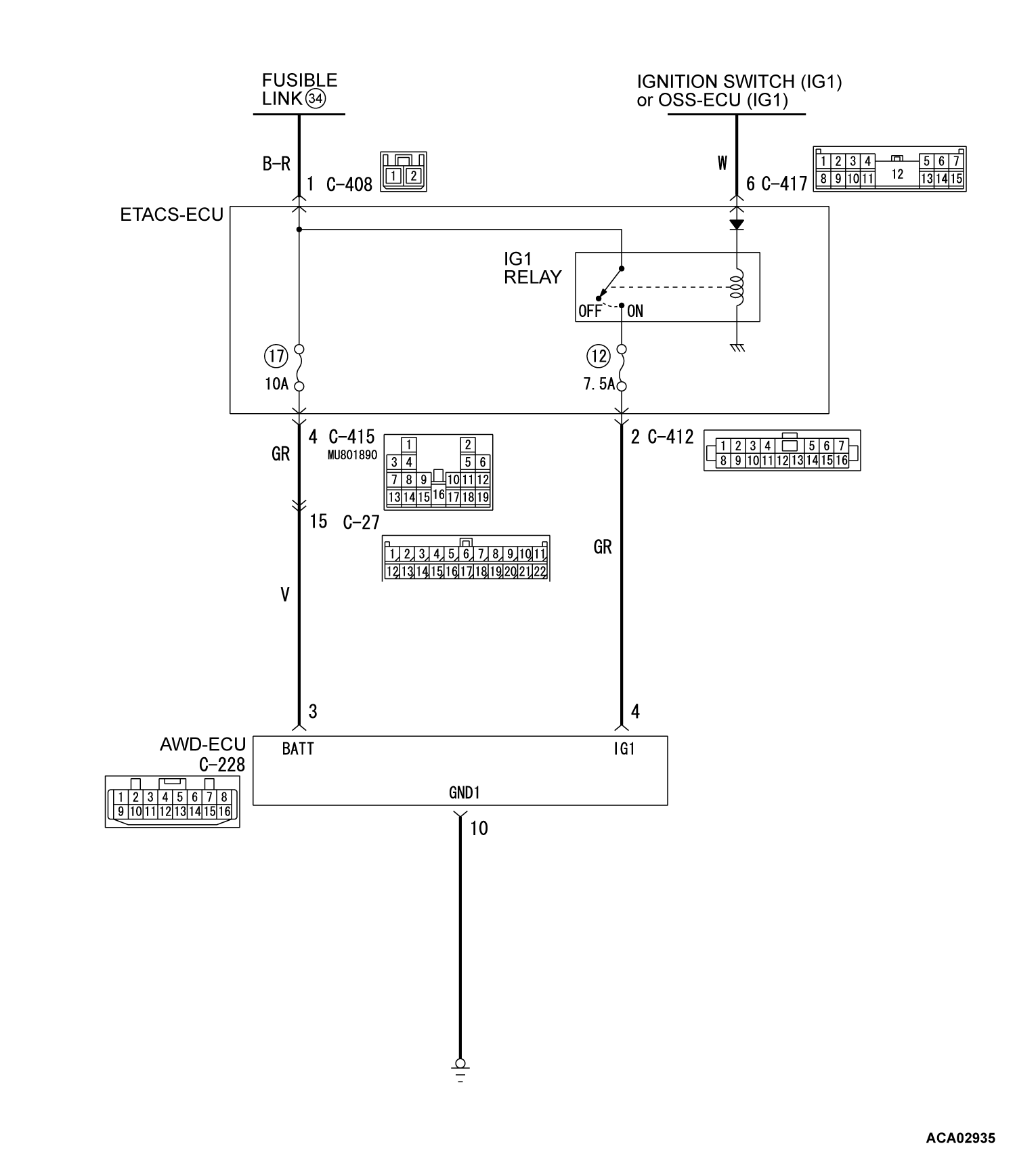
Inspection Procedure 1: Scan tool MB991958 cannot Communicate with the Electronic Control AWD System.
COMMENTS ON TROUBLE SYMPTOM
If scan tool MB991958 cannot communicate with the electronic control AWD system, the CAN bus lines may have a problem. If the electronic control AWD system is not in operation (in case of no AWD operation), the AWD-ECU power supply circuit system or AWD-ECU may have a problem.
TROUBLESHOOTING HINTS
- Damaged wiring harness and connectors
- AWD-ECU malfunction
DIAGNOSIS
STEP 1. Scan tool MB991958 CAN bus diagnostics
Use scan tool MB991958 to diagnose the CAN bus lines.
Is the check result normal?
STEP 2. Check the following connector:
Check the connectors below for improper engagement, terminal damage or terminal drawn in the connector case.
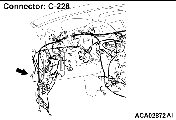
- C-228 AWD-ECU connector
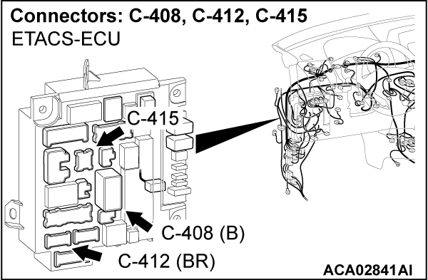
- C-408, C-412, C-415 ETACS-ECU connector
Are the connectors and terminals in good condition?
STEP 3. Voltage measurement at the AWD-ECU connector
(1) Disconnect the C-228 AWD-ECU connector.
(2) Turn the ignition switch to the "ON" position.
(3) Measure the voltage between the C-228 wiring harness side connector terminals No.3, No.4 (Ignition switch "ON") and the body ground.
OK: System voltage
Is the check result normal?
STEP 4. Wiring harness check
Check the wiring harness between the C-228 AWD-ECU connector (terminal No.4) and the C-412 ETACS-ECU connector (terminal No.2) for damage or other problem.
Is the wiring harness in good condition?
STEP 5. Resistance measurement at the AWD-ECU connector
(1) Disconnect the C-228 AWD-ECU connector.
(2) Measure the resistance between the C-228 wiring harness side connector terminals No. 10 and the body ground.
OK: Continuity exists (2 ohm or less)
Is the check result normal?
STEP 6. Wiring harness check
Check the wiring harness between the C-228 AWD-ECU connector (terminal No.10) and the body ground for damage or other problem.
Is the wiring harness in good condition?
STEP 7. Retest the system.
Does the malfunction occur again?
![[Previous]](../../../buttons/fprev.png)
![[Next]](../../../buttons/fnext.png)


