Inspection procedure 1: Communication with ECM is not possible
CIRCUIT OPERATION
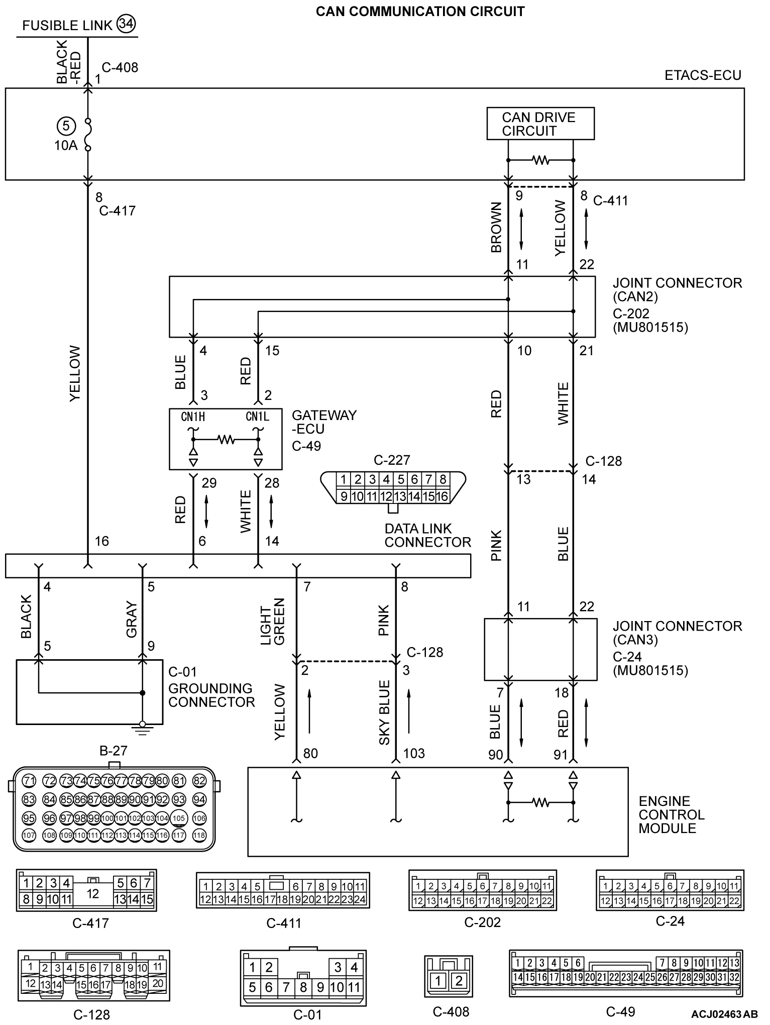
- Battery voltage is applied to the data link connector (terminal No. 16).
- The data link connector (terminal No. 4 and No. 5) is grounded to the vehicle body.
COMMENT
- When the communication between scan tool MB991958 and ECM is impossible, it can be suspected that the CAN bus line, power supply circuit of the data link connector, and/or grounding circuit are defective.
- Communication can not be achieved either, if a wrong vehicle type is selected on scan tool MB991958.
TROUBLESHOOTING HINTS (The most likely causes for this case:)
- Battery failed.
- Open or shorted data link connector circuit, harness damage or connector damage.
- CAN communication failed.
- Scan tool failed.
- ETACS-ECU failed.
- ECM failed.
DIAGNOSIS
Required Special Tool:
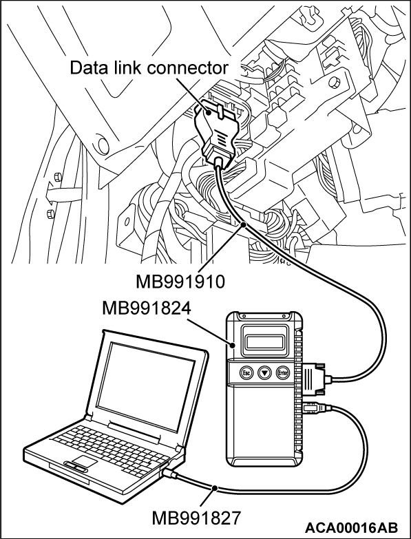
- MB991958: Scan Tool (M.U.T.-III Sub Assembly)
- MB991824: V.C.I.
- MB991827: USB Cable
- MB991910: Main Harness A
STEP 1. Check the vehicle communication interface (V.C.I.) MB991824 operations.
| caution | To prevent damage to scan tool MB991958, always turn the ignition switch to the "LOCK" (OFF) position before connecting or disconnecting scan tool MB991958. |
(1) Connect scan tool MB991958 to the data link connector.
(2) When the power of V.C.I. is turned to ON, the indicator lamp of the V.C.I. illuminates in green.
- The indicator lamp of the V.C.I. illuminates in green.
Is the indicator lamp of the V.C.I. illuminates in green?
STEP 2. Check the battery.
Refer to GROUP 54A, Battery - On-vehicle Service - Battery Test  .
. Replace the battery. Then confirm that the malfunction symptom is eliminated.
 .
.Are there any abnormalities?
 Replace the battery. Then confirm that the malfunction symptom is eliminated.
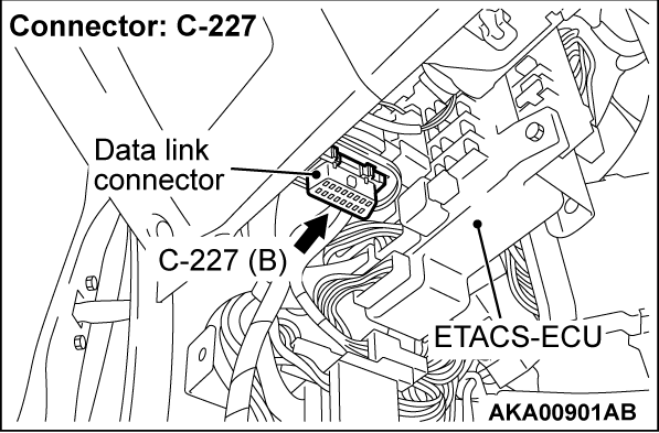
STEP 3. Check harness connector C-227 at data link connector for damage.
Is the harness connector in good condition?
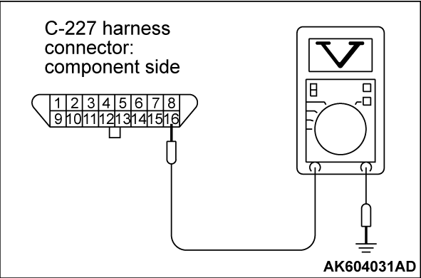
STEP 4. Measure the power supply voltage at data link connector harness side connector C-227.
Measure the voltage between terminal No. 16 and ground.
- Voltage should be battery positive voltage.
Is battery positive voltage (approximately 12 volts) present?
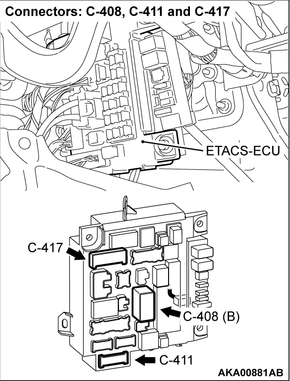
STEP 5. Check harness connector C-417 at ETACS-ECU for damage.
Is the harness connector in good condition?
STEP 6. Check for open circuit and short circuit to ground between ETACS-ECU connector C-417 (terminal No. 8) and data link connector C-227 (terminal No. 16).
Is the harness wire in good condition?
 Repair it. Then confirm that the malfunction symptom is eliminated.
STEP 7. Check harness connector C-408 at ETACS-ECU for damage.
Is the harness connector in good condition?
STEP 8. Check for open circuit and short circuit to ground between battery and ETACS-ECU connector C-408 (terminal No. 1).
Is the harness wire in good condition?
 Check No. 5 fuse in the ETACS-ECU, and replace as required. If the fuse is in good condition, replace the ETACS-ECU. Then confirm that the malfunction symptom is eliminated.
 Repair it. Then confirm that the malfunction symptom is eliminated.
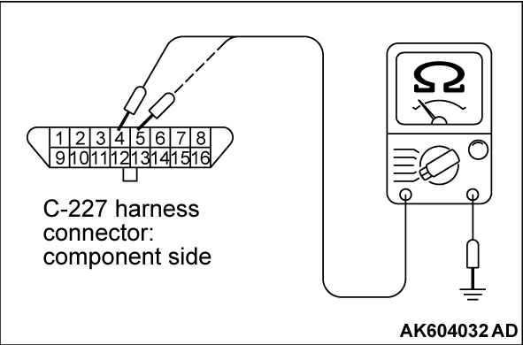
STEP 9. Check the continuity at data link connector harness side connector C-227.
Check for the continuity between terminal No. 4, No. 5 and ground. Repair harness wire between data link connector C-227 (terminals No. 4, No. 5) and ground because of open circuit or harness damage. Then confirm that the malfunction symptom is eliminated.
- Continuity (2 ohms or less)
Does continuity exist?
 Repair harness wire between data link connector C-227 (terminals No. 4, No. 5) and ground because of open circuit or harness damage. Then confirm that the malfunction symptom is eliminated.
STEP 10. Check harness connector C-408 and C-417 at ETACS-ECU for damage.
Are the harness connectors in good condition?
STEP 11. Check the continuity at ETACS-ECU connectors C-408 and C-417.
(1) Disconnect the connectors C-408, C-417 and measure at the ETACS-ECU side.
(2) Check for the continuity between terminal No. 1 (C-408) and terminal No. 8 (C-417).
- Continuity
Does continuity exist?
 Check No. 5 fuse in the ETACS-ECU, and replace as required. If the fuse is in good condition, replace the ETACS-ECU. Then confirm that the malfunction symptom is eliminated.
STEP 12. Check for harness damage between battery and ETACS-ECU connector C-408 (terminal No. 1).
Is the harness wire in good condition?
 Repair it. Then confirm that the malfunction symptom is eliminated.
STEP 13. Check for harness damage between ETACS-ECU connector C-417 (terminal No. 8) and data link connector C-227 (terminal No. 16).
Is the harness wire in good condition?
 Refer to the scan tool MB991958 reference manual.
 Repair it. Then confirm that the malfunction symptom is eliminated.
STEP 14. Using scan tool MB991958, diagnose CAN bus line.
(1) Turn the ignition switch to the "ON" position.
(2) Diagnose CAN bus line.
(3) Turn the ignition switch to the "LOCK" (OFF) position.
Is the CAN bus line normal?
![[Previous]](../../../buttons/fprev.png)
![[Next]](../../../buttons/fnext.png)
