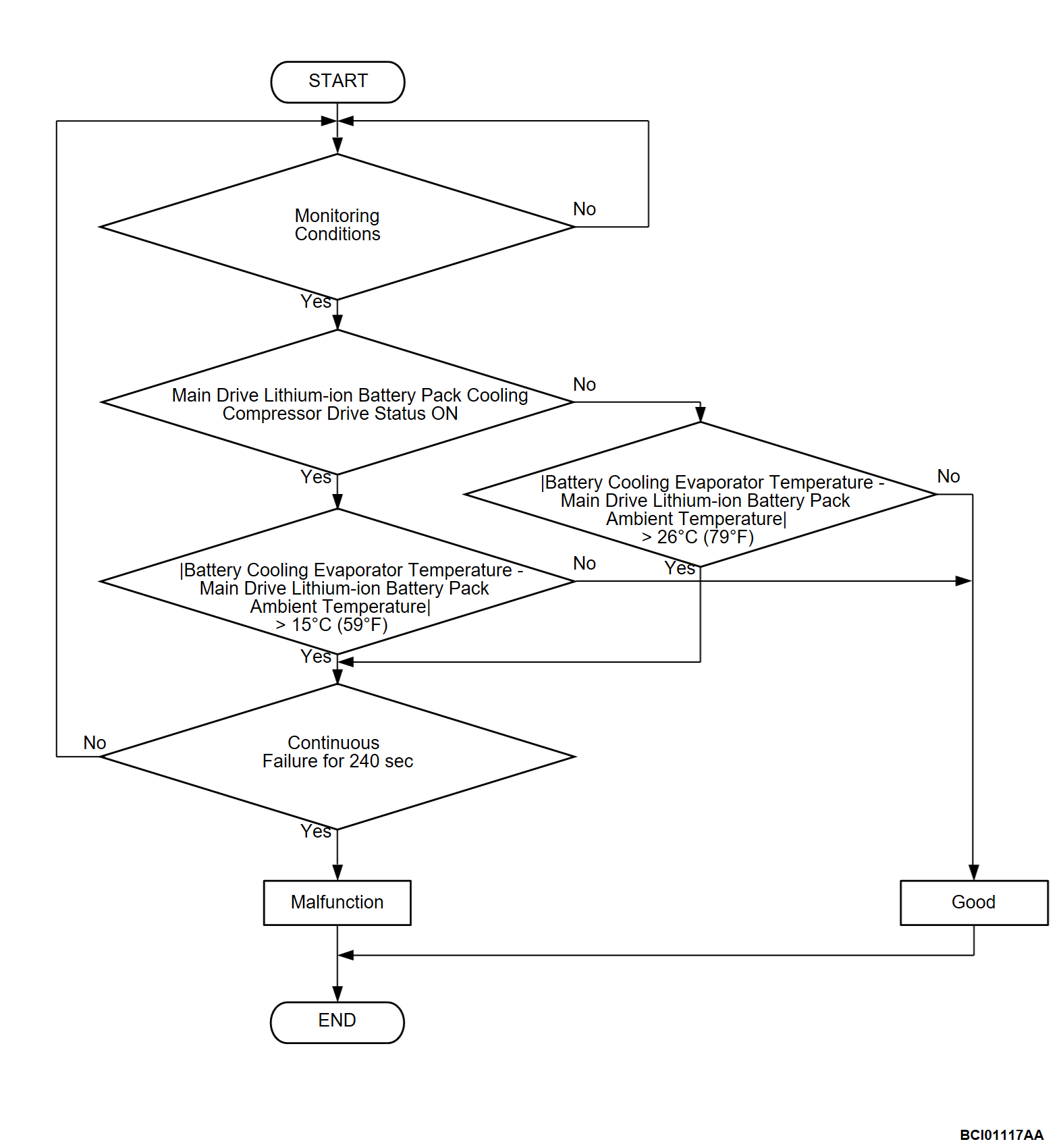
DTC P1F0C: BAT.Cooling EVAP/PTC heater TEMP
| caution | Whenever ECU is replaced, ensure that the CAN bus lines are normal. |
DESCRIPTIONS OF MONITOR METHODS
- Uniform temperature in the driving battery is achieved after the driving battery cooling fan has operated for an adequate amount of time.
- The monitor is enabled during the following condition.
- The driving battery cooling fan operates for 180 seconds or more.
MONITOR EXECUTION
- Continuous
MONITOR EXECUTION CONDITIONS (Other monitor and Sensor)
Other Monitor (There is no temporary DTC stored in memory for the item monitored below)
- Not applicable
Sensor (The sensor below is determined to be normal)
- Driving battery ambient temperature sensor
DTC SET CONDITIONS
Check Conditions
- The heater controller assembly (A/C-ECU) power supply voltage is between 10 and 16 volts.
- The drive battery cooling fan drive status is on.
- Time after above condition satisfied is more than 180 seconds.
- The drive battery cooling compressor drive status is on.
Judgment Criterion
- The difference between the battery cooling evaporator temperature value and the driving battery ambient temperature value changes to 15°C (59°F) or more within 240 seconds.
Check Conditions
- The heater controller assembly (A/C-ECU) power supply voltage is between 10 and 16 volts.
- The drive battery cooling fan drive status is on.
- Time after above condition satisfied is more than 180 seconds.
- The drive battery cooling compressor drive status is off.
Judgment Criterion
- The difference between the battery cooling evaporator temperature value and the driving battery ambient temperature value changes to 26°C (79°F) or more within 240 seconds.
PROBABLE CAUSES
- Malfunction of the CAN bus
- Malfunction of the heater controller assembly (A/C-ECU)
- Malfunction of the PHEV-ECU.
DIAGNOSIS
STEP 1. Using scan tool (M.U.T.-IIISE), check whether the other DTC is set.
Scan tool (M.U.T.-IIISE) other system DTC [heater controller assembly (A/C-ECU)] (Refer to  ).
).
 ).
).Is the DTC set?
![[Previous]](../../../buttons/fprev.png)
![[Next]](../../../buttons/fnext.png)


