DIAGNOSTIC FUNCTION
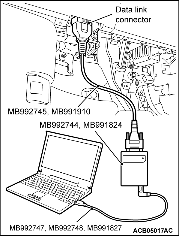
HOW TO CONNECT THE SCAN TOOL (M.U.T.-IIISE)
Required Special Tools:
- MB992744: Vehicle communication interface-Lite (V.C.I.-Lite)
- MB992745: V.C.I.-Lite main harness A
- MB992747: V.C.I.-Lite USB cable short
- MB992748: V.C.I.-Lite USB cable long
- MB991958: Scan Tool (M.U.T.-III Sub Assembly)
- MB991824: Vehicles Communication Interface (V.C.I.)
- MB991827: M.U.T.-III USB Cable
- MB991910: M.U.T.-III Main Harness A (Vehicles with CAN communication system)
| caution | To prevent damage to scan tool (M.U.T.-IIISE), always turn the electric motor switch to the OFF position before connecting or disconnecting scan tool (M.U.T.-IIISE). |
1. Ensure that the electric motor switch is at the OFF position.
2. Start up the personal computer.
3. Connect special tool MB992747/M992748 or special tool MB991827 to special tool MB992744 or special tool MB991824 and the personal computer.
4. Connect special tool MB992745 or special tool MB991910 to special tool MB992744 or special tool MB991824.
5. Connect special tool MB992745 or special tool MB991910 to the data link connector.
| note | When the special tool MB992745 is connected to the data link connector, the special tool MB992744 indicator light will be illuminated in a green color. |
6. Turn the power switch of special tool MB991824 to the "ON" position. <When using the special tool MB991824>
| note | When special tool MB991824 is energized, special tool MB991824 indicator light will be illuminated in a green color. |
7. Start the M.U.T.-III system on the personal computer.
| note | Disconnecting scan tool (M.U.T.-IIISE) is the reverse of the connecting sequence, making sure that the electric motor switch is at the OFF position. |
HOW TO READ AND ERASE DIAGNOSTIC TROUBLE CODES
Required Special Tools:
- MB992744: Vehicle communication interface-Lite (V.C.I.-Lite)
- MB992745: V.C.I.-Lite main harness A
- MB992747: V.C.I.-Lite USB cable short
- MB992748: V.C.I.-Lite USB cable long
- MB991958: Scan Tool (M.U.T.-III Sub Assembly)
- MB991824: Vehicles Communication Interface (V.C.I.)
- MB991827: M.U.T.-III USB Cable
- MB991910: M.U.T.-III Main Harness A (Vehicles with CAN communication system)
| note | If the battery voltage is low, diagnostic trouble codes will not be set. Check the battery if scan tool (M.U.T.-IIISE) does not display. |
1. Connect scan tool (M.U.T.-IIISE) to the data link connector.
2. Turn the electric motor switch to the ON position.
3. Select "STV" .
4. Select "Air Conditioner".
5. Select "Diagnostic Trouble Code" to read the DTC.
6. If a DTC is set, it is shown.
7. Choose "Erase DTCs" to erase the DTC.
HOW TO DIAGNOSE THE CAN BUS LINES
Required Special Tools:
- MB992744: Vehicle communication interface-Lite (V.C.I.-Lite)
- MB992745: V.C.I.-Lite main harness A
- MB992747: V.C.I.-Lite USB cable short
- MB992748: V.C.I.-Lite USB cable long
- MB991958: Scan Tool (M.U.T.-III Sub Assembly)
- MB991824: Vehicles Communication Interface (V.C.I.)
- MB991827: M.U.T.-III USB Cable
- MB991910: M.U.T.-III Main Harness A (Vehicles with CAN communication system)
1. Connect scan tool (M.U.T.-IIISE) to the data link connector.
2. Turn the electric motor switch to the ON position.
3. Select "CAN bus diagnosis" from the System select screen.
4. When the optional equipment screen is displayed, choose the one which the vehicle is fitted with, and then select the "OK" button.
CHECK OF FREEZE FRAME DATA
To detect fault and set the DTC, the ETACS-ECU obtains data before the confirmation of the DTC and data when the DTC is confirmed, and then stores the current condition of the ETACS-ECU. By analyzing each data from scan tool (M.U.T.-IIISE), the troubleshooting can be performed more efficiently. Display items of the freeze frame data are as follows.
Display item list
| Item No. | Item name | Data item | Unit |
| 1 | Odometer | Total driving distance after the DTC is generated | km (mile) |
| 2 | Ignition cycle | Number of times the electric motor switch is turned "OFF (OFF or ACC)" after the past failure transition. | Number of counts is displayed. |
| 4 | Accumulated minute | Cumulative time for current malfunction of DTC | min |
OBD-II DRIVE CYCLE
All kinds of diagnostic trouble codes (DTCs) can be monitored by carrying out a short drive according to the following 5 drive cycle patterns. In other words, doing such a drive regenerates any kind of trouble which involves illuminating the Malfunction Indicator light (SERVICE ENGINE SOON or Check Engine light) and verifies the repair procedure has been eliminated [the trouble the Malfunction Indicator light (SERVICE ENGINE SOON or Check Engine light) is no longer illuminated].| caution | Two technicians should always be in the vehicle when carrying out a test. |
| note | Check that the diagnosis trouble code (DTC) is not set before driving the OBD-II drive cycle. Erase the DTC if it has been set. |
DRIVE CYCLE PATTERN LIST
PATTERN 1
| Inspection conditions | Use scan tool (M.U.T.-IIISE) to check the PHEV-ECU data list and the BMU data list.
| ||||
| Test procedure |
|
PATTERN 2
| Inspection conditions | Use scan tool (M.U.T.-IIISE) to check the PHEV-ECU data list and the BMU data list.
| ||||
| Test procedure |
|
PATTERN 3
| Inspection conditions | Use scan tool (M.U.T.-IIISE) to check the PHEV-ECU data list.
| ||||
| Test procedure |
|
PATTERN 4
| Inspection conditions | Use scan tool (M.U.T.-IIISE) to check the PHEV-ECU data list.
| ||||
| Test procedure |
|
PATTERN 5
| Inspection conditions | Use scan tool (M.U.T.-IIISE) to check the PHEV-ECU data list.
| ||||
| Test procedure |
|
![[Previous]](../../../buttons/fprev.png)
![[Next]](../../../buttons/fnext.png)

