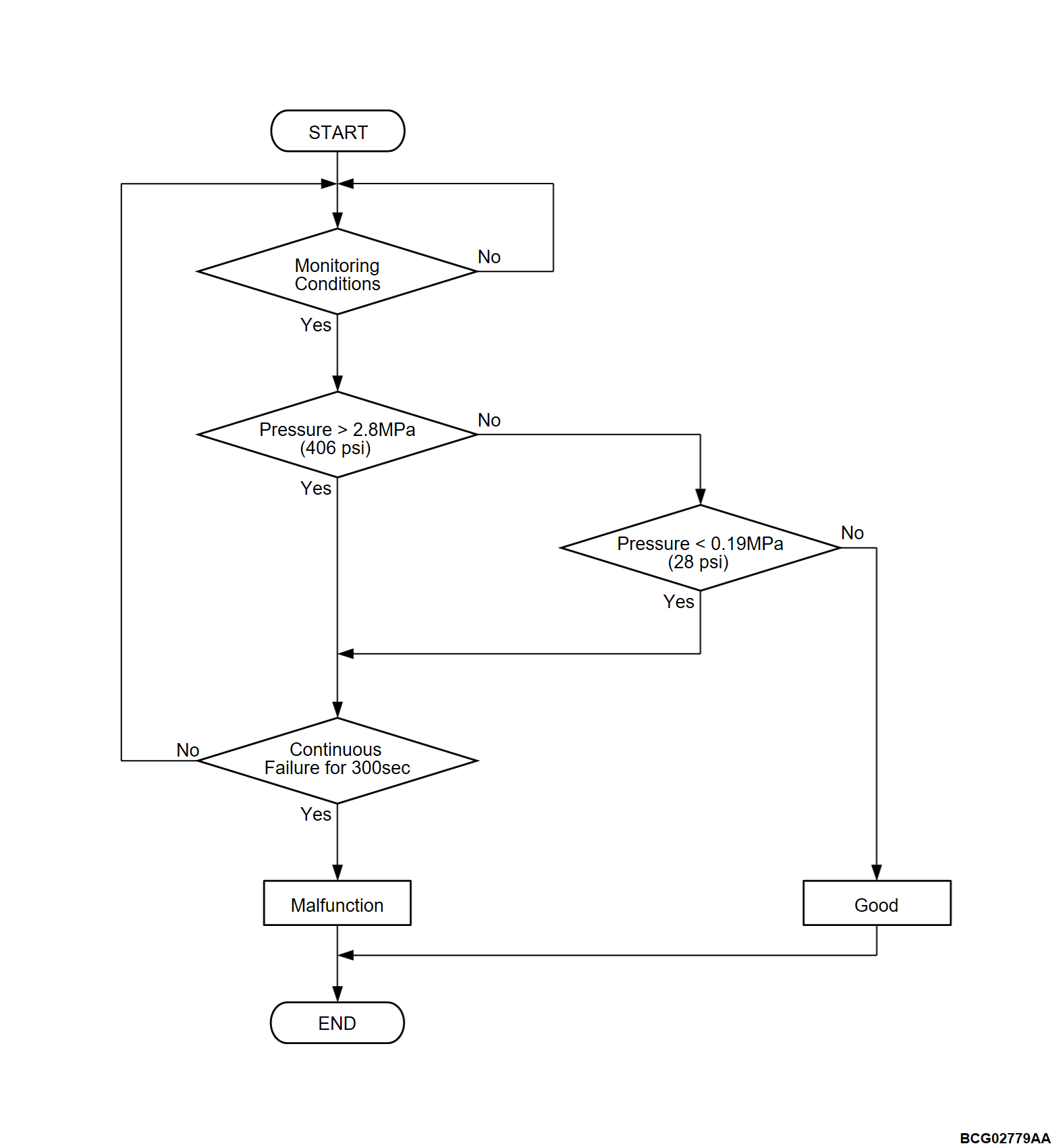
DTC P0531: Refrigerant PRS. sensor range
| caution | Whenever ECU is replaced, ensure that the CAN bus lines are normal. |
DESCRIPTIONS OF MONITOR METHODS
- The electric compressor doesn't operate when the refrigerant pressure is less then 0.19 MPa (28 psi) or more than 2.8 MPa (406 psi).
- The electric compressor doesn't work when the refrigerant temperature is less than 0°C (32°F) according to correlation between the refrigerant pressure and refrigerant temperature so the monitor is not preformed under the condition.
- The monitor uses the driving battery temperature minimum value and engine intake air temperature instead of the refrigerant temperature to enable diagnostics.
MONITOR EXECUTION
- Continuous
MONITOR EXECUTION CONDITIONS (Other monitor and Sensor)
Other Monitor (There is no temporary DTC stored in memory for the item monitored below)
- Not applicable
Sensor (The sensor below is determined to be normal)
- Battery cooling evaporator temperature sensor
- Driving battery temperature sensor
- Intake air temperature sensor
DTC SET CONDITIONS
Check Conditions
- The heater controller assembly (A/C-ECU) power supply voltage is between 10 and 16 volts.
- The battery cooling evaporator temperature is more than 4°C (39°F).
- The drive battery temperature minimum value is more than 15°C (59°F).
- The intake air temperature is more than 0°C (32°F).
Judgment Criterion
- Change the A/C pressure sensor pressure is more than 2.8 MPa (406 psi) (4.253 volts) for 300 seconds.
Judgment Criterion
- Change the A/C pressure sensor pressure is less than 0.19 MPa (28 psi) (0.382 volt) for 300 seconds.
PROBABLE CAUSES
- Malfunction of the CAN bus
- Malfunction of the heater controller assembly (A/C-ECU)
- Malfunction of the PHEV-ECU.
DIAGNOSIS
STEP 1. Using scan tool (M.U.T.-IIISE), check whether the other DTC is set.
Scan tool (M.U.T.-IIISE) other system DTC [heater controller assembly (A/C-ECU)] (Refer to  ).
).
 ).
).Is the DTC set?
![[Previous]](../../../buttons/fprev.png)
![[Next]](../../../buttons/fnext.png)


