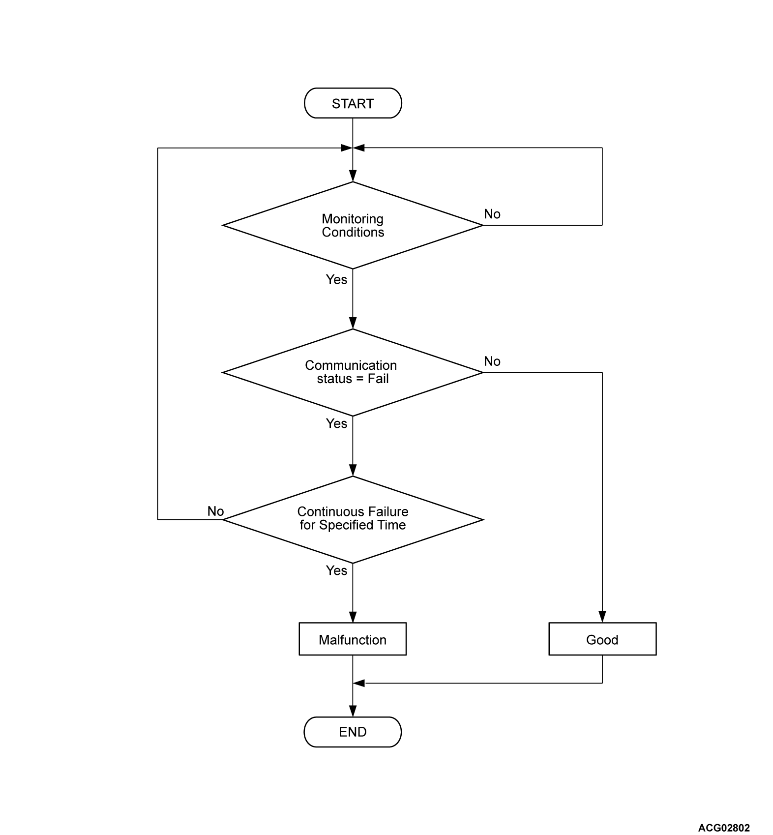
DTC U0112: SUB-BMU Signal Timeout
| caution |
MONITOR EXECUTION
- Continuous
MONITOR EXECUTION CONDITIONS (Other monitor and Sensor)
Other Monitor (There is no temporary DTC set in memory for the item monitored below)
- Not applicable
Sensor (The sensor below is determined to be normal)
- Not applicable
DTC SET CONDITIONS
Check Conditions
- battery management unit (BMU) power supply voltage is 8 volts to 16 volts.
- Time after above conditions satisfy is more than 2 seconds.
Judgment Criterion
- Unable to receive sub battery management unit (BMU) signals through the CAN bus line for 0.3 second.
OBD-II DRIVE CYCLE PATTERN
FAIL-SAFE AND BACKUP FUNCTION
- Not available
PROBABLE CAUSES
- The harness and connector is failed.
- CAN line harness damage or connector damage.
- The battery management unit (BMU) is failed.
- The sub-battery management unit [BMU (SUB)] is failed.
DIAGNOSIS
Required Special Tools
- MB991658: Test harness
STEP 1. Using scan tool (M.U.T.-IIISE), check whether the DTC is set.
Check whether DTC No. P1AD3, P1AD4, P1AD5, P1AD6, P1AD7, P1AD9, P1ADA, P1ADB, P1ADC and P1ADD are set at the same time.
Is the DTC set?
STEP 2. Measure the resistance at main drive lithium-ion battery connector.
(1) Disconnect the D-33 main drive lithium-ion battery connector, and measure at the wiring harness side.
(2) Check the resistance between the D-33 main drive lithium-ion battery connector (terminal No.3) and body ground.
OK: Continuity exists (2 Ω or less)
Is the check result normal?
STEP 3. Measure the voltage measurement at main drive lithium-ion battery connector
(1) Disconnect the D-32 main drive lithium-ion battery connector, and measure at the wiring harness side.
(2) Turn on the power supply mode of the electric motor switch.
(3) Check the voltage between the D-32 main drive lithium-ion battery connector (terminal No.5) and body ground.
OK: Battery voltage
Is the check result normal?
STEP 4. Check of open circuit, short to ground or short to power supply in CNBL, CNBH line between main drive lithium-ion battery connector and BMU connector.
| caution | When measuring the resistance, disconnect the negative 12V starter battery terminal. |
Is the check result normal?
STEP 5. Resistance measurement at BMU connector.
(1) Remove the BMU, and measure at the equipment side.
(2) Resistance between D-203 BMU connector terminal Nos.37 and 38.
OK: 120 ± 20 Ω
Is the check result normal?
STEP 6. Test the OBD-II drive cycle.
(2) Check if the DTC is set.
Is the DTC set?
STEP 7. Check of open circuit and damage circuit in line between SUB-BMU connector and joint connector.
(2) Disconnect the I-02 joint connector (CAN7) and SUB-BMU connector, and measure at the wiring harness side.
(3) Check the line between the following terminals.
- Between the SUB-BMU connector (IGCT terminal) and I-17 joint connector (17) (terminal No.7).
- Between the SUB-BMU connector (GND terminal) and I-16 joint connector (18) (terminal No.9).
- Between the SUB-BMU connector (CANH terminal) and I-02 joint connector (CAN7) (terminal No.14).
- Between the SUB-BMU connector (CANL terminal) and I-02 joint connector (CAN7) (terminal No.3).
Is the check result normal?
![[Previous]](../../../buttons/fprev.png)
![[Next]](../../../buttons/fnext.png)


