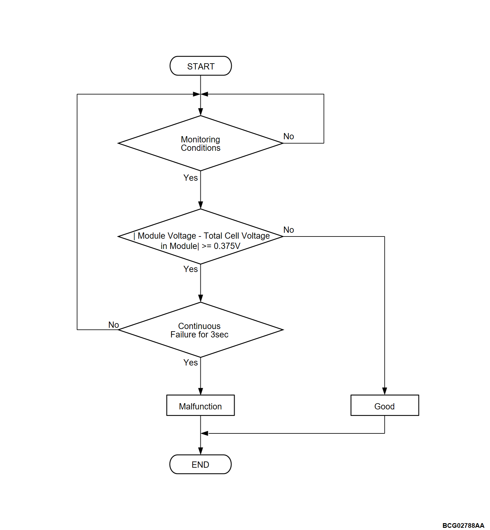
DTC P0B3C, P0B41, P0B46, P0B4B, P0B50, P0B5A, P0B5F, P0B64, P0B69, P0B6E: Cell Voltage Sensor Rationality
| caution | Whenever ECU is replaced, ensure that the CAN bus lines are normal. |
MONITOR EXECUTION
- Continuous
MONITOR EXECUTION CONDITIONS (Other monitor and Sensor)
Other Monitor (There is no temporary DTC set in memory for the item monitored below)
- Main drive lithium-ion battery cell voltage monitor
- Battery CAN monitor
Sensor (The sensor below is determined to be normal)
- Not applicable
DTC SET CONDITIONS
Check Conditions
- battery management unit (BMU) power supply voltage is 8 volts to 16 volts.
- Time after above conditions satisfy is more than 2 seconds.
Judgment Criterion
- The absolute value of the difference between the value of the voltage between the terminal for the end of a module and the sum total of cell voltages in the module changes to 0.375 volts or more and the state continues for 3 seconds.
FAIL-SAFE AND BACKUP FUNCTION
- Not available
PROBABLE CAUSE
- The cell monitoring unit (CMU) in the main drive lithium-ion battery is failed.
DIAGNOSIS
STEP 1. Test the OBD-II drive cycle.
(2) Check if the DTC is set.
Is the DTC set?
![[Previous]](../../../buttons/fprev.png)
![[Next]](../../../buttons/fnext.png)


