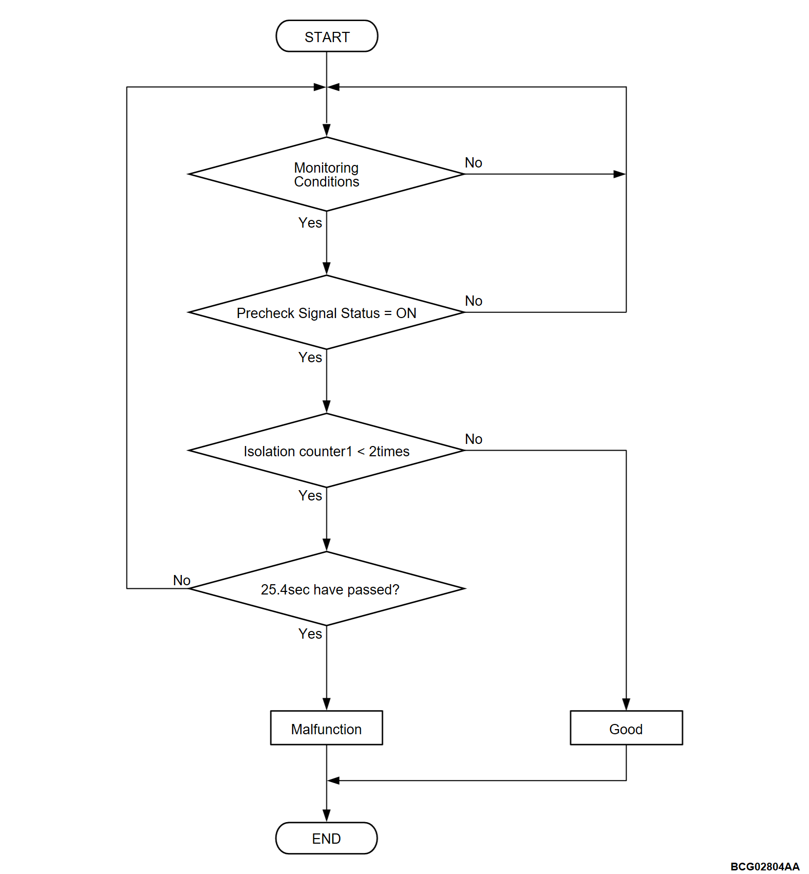
DTC P0AA8: Leak Sensor Detection Circuit Open
DESCRIPTIONS OF MONITOR METHODS
- The monitor executes immediately after hybrid system launch.
- Precheck circuit can simulate isolation state intentionally when "Precheck signal status is on".
- The monitor judges circuit malfunction when the monitor cannot detect the isolation state at "Precheck signal status is on".
- The monitor detects a malfunction by using "Isolation counter 1".
MONITOR EXECUTION
- Once per driving cycle
MONITOR EXECUTION CONDITIONS (Other monitor and Sensor)
Other Monitor (There is no temporary DTC stored in memory for the item monitored below)
- Not applicable
Sensor (The sensor below is determined to be normal)
- Not applicable
DTC SET CONDITIONS
Check Conditions
- BMU (SUB) power supply voltage is 8 volts to 16 volts.
- Time after above conditions satisfy is more than 3.5 seconds.
- Precheck signal status is on.
Judgment Criterion
- Isolation counter 1 is less than 2 times for 25.4 seconds.
FAIL-SAFE AND BACKUP FUNCTION
- Not available
PROBABLE CAUSES
- Ground fault of high voltage system component.
- The main drive lithium-ion battery ground fault detector failed.
- Open circuits of main drive lithium-ion battery ground fault detector circuit, short circuits to ground, short circuits to power supply system or damage; poor contact of connector.
- The sub-battery management unit [BMU (SUB)] is failed.
DIAGNOSIS
Required Special Tools
- MB991658: Test harness
| danger | When high voltage system components are serviced, be sure to pull service plugs to shut down high voltage before servicing (Refer to  ). ). |
| danger | When pulling service plugs, wear the specified protective equipment (Refer to  ). ). |
STEP 1. Measure the resistance at main drive lithium-ion battery connector.
(1) Disconnect the D-34 main drive lithium-ion battery connector, and measure at the wiring harness side.
(2) Check the resistance between the D-34 main drive lithium-ion battery connector (terminal No.6) and body ground.
OK: Continuity exist (2 Ω or less)
Is the check result normal?
STEP 2. Check of open circuit in line between main drive lithium-ion battery connector and sub-battery management unit [BMU (SUB)] connector.
(2) Disconnect the sub-battery management unit [BMU (SUB)] connector, and measure at the wiring harness side.
(3) Check the resistance between the sub-battery management unit [BMU (SUB)] connector (LGND terminal) and D-34 main drive lithium-ion battery connector (terminal No.6).
OK: Continuity exists (2 Ω or less)
(4) Check the resistance between the sub-battery management unit [BMU (SUB)] connector (TP1 terminal) and sub-battery management unit [BMU (SUB)] connector (TP2 terminal). <High voltage>
OK: Continuity exists (2 Ω or less)
Is the check result normal
![[Previous]](../../../buttons/fprev.png)
![[Next]](../../../buttons/fnext.png)


