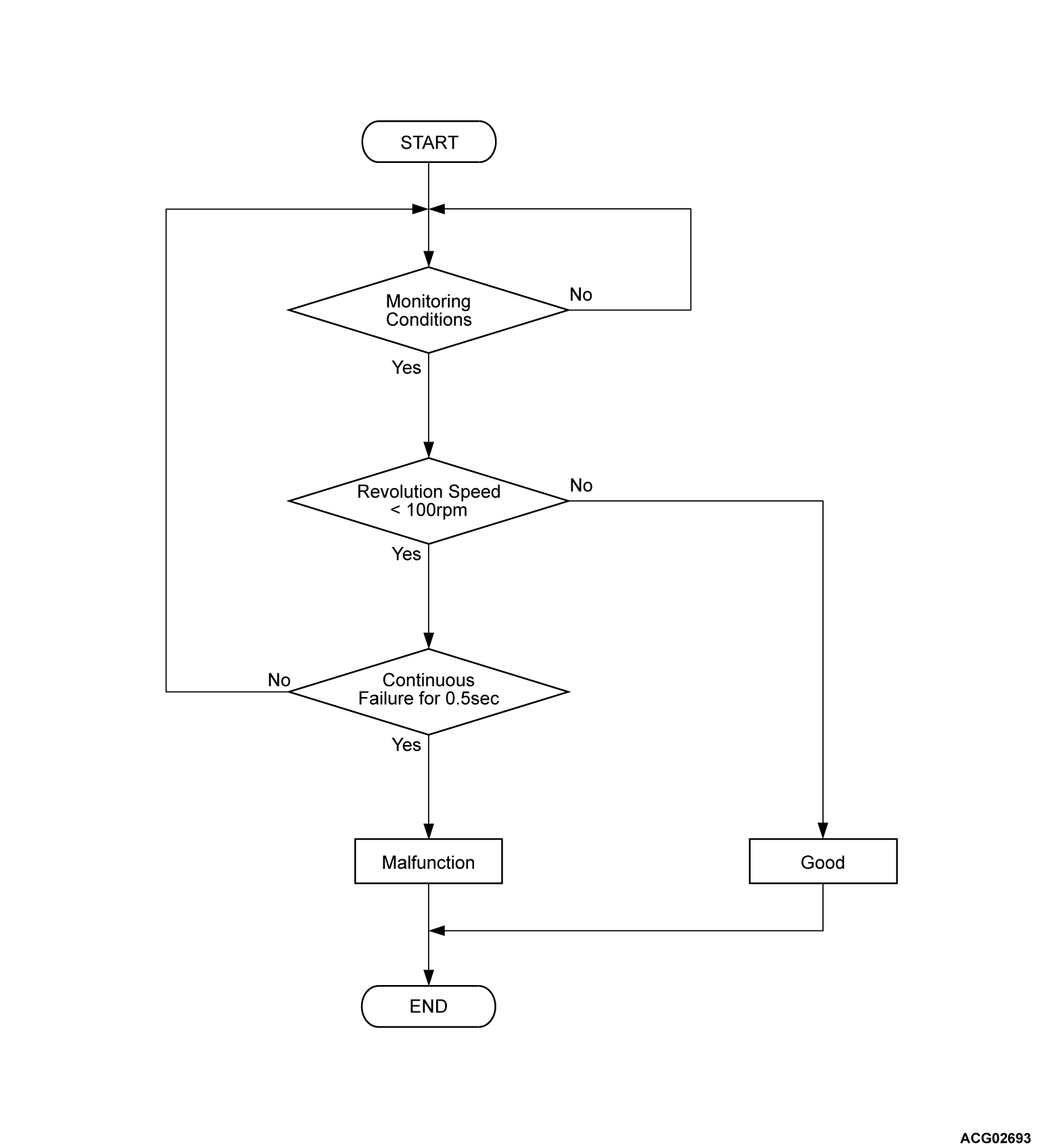
DTC P10D9: Water pump speed sensor circuit
| caution | Before replacing the ECU, ensure that the communication circuit is normal. |
MONITOR EXECUTION
Continuous
MONITOR EXECUTION CONDITIONS (Other monitor and Sensor)
Other Monitor (There is no temporary DTC stored in memory for the item monitored below)
- Not applicable
Sensor (The sensor below is determined to be normal)
- Not applicable
Check Conditions
- The PHEV-ECU power supply voltage is more than 9.0 volts.
- Time after above conditions satisfy is more than 2 seconds.
Judgment Criterion
- When the rotation speed less than 100 rpm continues for 0.5 seconds
PROBABLE CAUSES
- Damaged harness or connector.
- Malfunction of the electric water/oil pump relay.
- Malfunction of the electric water pump.
- Malfunction of the PHEV-ECU.
DIAGNOSIS
Required Special Tools
- MB991223: Wiring harness set
- MB992006: Extra fine probe
STEP 1. Using scan tool (M.U.T.-IIISE), check the data list.
(1) Turn on the power supply mode of the electric motor switch (Ready: OFF).
(2) Check that the following data list display contents are normal (Refer to  ).
).
 ).
).Data list
- Item 305: WP speed
OK: 500 r/min
Is the check result normal?
STEP 2. Water/oil pump relay check.
STEP 3. Voltage measurement at water/oil pump relay.
(1) Disconnect the water/oil pump relay, and measure at the wiring harness side.
(2) Turn off to on the power supply mode of the electric motor switch.
(3) Measure the voltage between the harness side connector (terminal No.2) and body ground.
OK: Approximately 12 volts (battery positive voltage).
Is the check result normal?
STEP 4. Check the power supply line for open circuit. (IGCT control relay and the water/oil pump relay).
Check the wiring harness between IGCT control relay and the water/oil pump relay connector (terminal No.2).
Is the check result normal?
STEP 5. Check the signal line for short to ground circuit (water/oil pump relay and the PHEV-ECU).
Check the wiring harness between water/oil pump relay connector (terminal No.1) and the PHEV-ECU connector (terminal WPR-).
Is the check result normal?
STEP 6. Check the power supply line for open circuit and short to ground circuit (water/oil pump relay and the electric water pump).
Check the wiring harness between water/oil pump relay connector (terminal No.3) and the electric water pump connector (terminal No.1).
Is the check result normal?
STEP 7. Check the power ground line for open circuit (electric water pump and the ground).
Check the wiring harness between electric water pump connector (terminal No.4) and the ground.
Is the check result normal?
STEP 8. Check the signal line for open circuit or short to ground circuit (electric water pump connector and the PHEV-ECU).
Check the wiring harness between electric water pump connector (terminal No.3) and the PHEV-ECU connector (terminal WPN).
Is the check result normal?
STEP 9. Check the ground line for open circuit or short to ground circuit (electric water pump connector and the PHEV-ECU).
Check the wiring harness between electric water pump connector (terminal No.2) and the PHEV-ECU connector (terminal WP).
Is the check result normal?
![[Previous]](../../../buttons/fprev.png)
![[Next]](../../../buttons/fnext.png)


