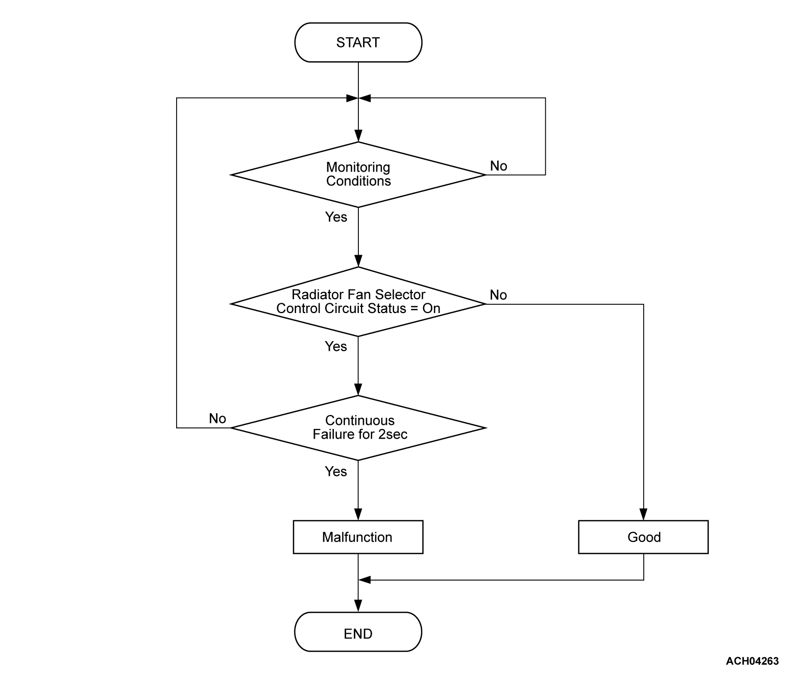
DTC P10DE: Radiator fan DIM/Relay circuit L
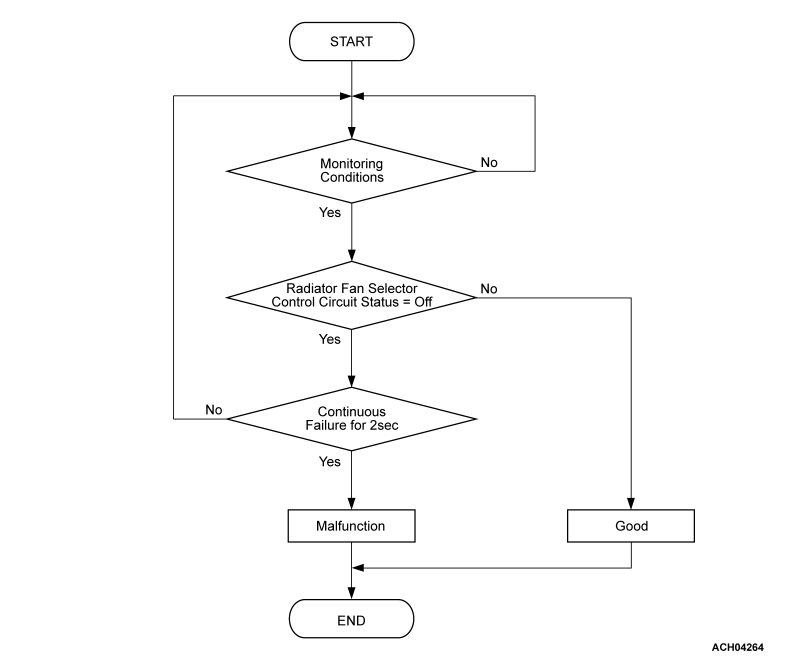
DTC P10DF: Radiator fan DIM/Relay circuit H
DTC P10DF: Radiator fan DIM/Relay circuit H
| caution | Whenever ECU is replaced, ensure that the CAN bus lines are normal. |
| note | Display on scan tool (M.U.T.-IIISE): Radiator fan DIM/relay→Designation in workshop manual: Fan control relay |
MONITOR EXECUTION
- Continuous
MONITOR EXECUTION CONDITIONS (Other monitor and Sensor)
Other Monitor (There is no temporary DTC stored in memory for the item monitored below)
- Not applicable
Sensor (The sensor below is determined to be normal)
- Not applicable
DTC SET CONDITIONS
Check Conditions <DTC P10DE>
- The PHEV-ECU power supply voltage is more than 9.0 volts.
- The fan control relay activation command off.
Judgment Criterion <DTC P10DE>
- The radiator fan relay is on for 2 seconds.
Check Conditions <DTC P10DF>
- The PHEV-ECU power supply voltage is more than 9.0 volts.
- The fan control relay activation command on.
Judgment Criterion <DTC P10DF>
- The radiator fan relay is off for 2 seconds.
OBD-II DRIVE CYCLE PATTERN <DTC P10DE>
OBD-II DRIVE CYCLE PATTERN <DTC P10DF>
PROBABLE CAUSES
- Damaged harness or connector.
- Malfunction of the fan control relay.
- Malfunction of the PHEV-ECU.
DIAGNOSIS
Required Special Tools
- MB991223: Wiring harness set
- MB992006: Extra fine probe
STEP 1. Check the fan control relay.
Refer to GROUP 14A - On-vehicle Service, Cooling Fan Relay Continuity Check  .
.
 .
.Is the check result normal?
STEP 2. Check the fusible link SBF4 (relay box 1) and SBF1 (relay box 1).
STEP 3. Check the power supply line for open circuit and short to ground circuit [fusible link (SBF1) and the PHEV-ECU].
Check the wiring harness between fusible link (SBF1) and the PHEV-ECU connector (terminal RFDR).
Is the check result normal?
STEP 4. Using scan tool (M.U.T.-IIISE), check whether the DTC is set again.
Recheck the DTC.
(1) Erase the DTC.
(2) Turn off the power supply mode of the electric motor switch.
(3) Turn on the power supply mode of the electric motor switch.
(4) Check the DTC.
Is the DTC set?
![[Previous]](../../../buttons/fprev.png)
![[Next]](../../../buttons/fnext.png)


