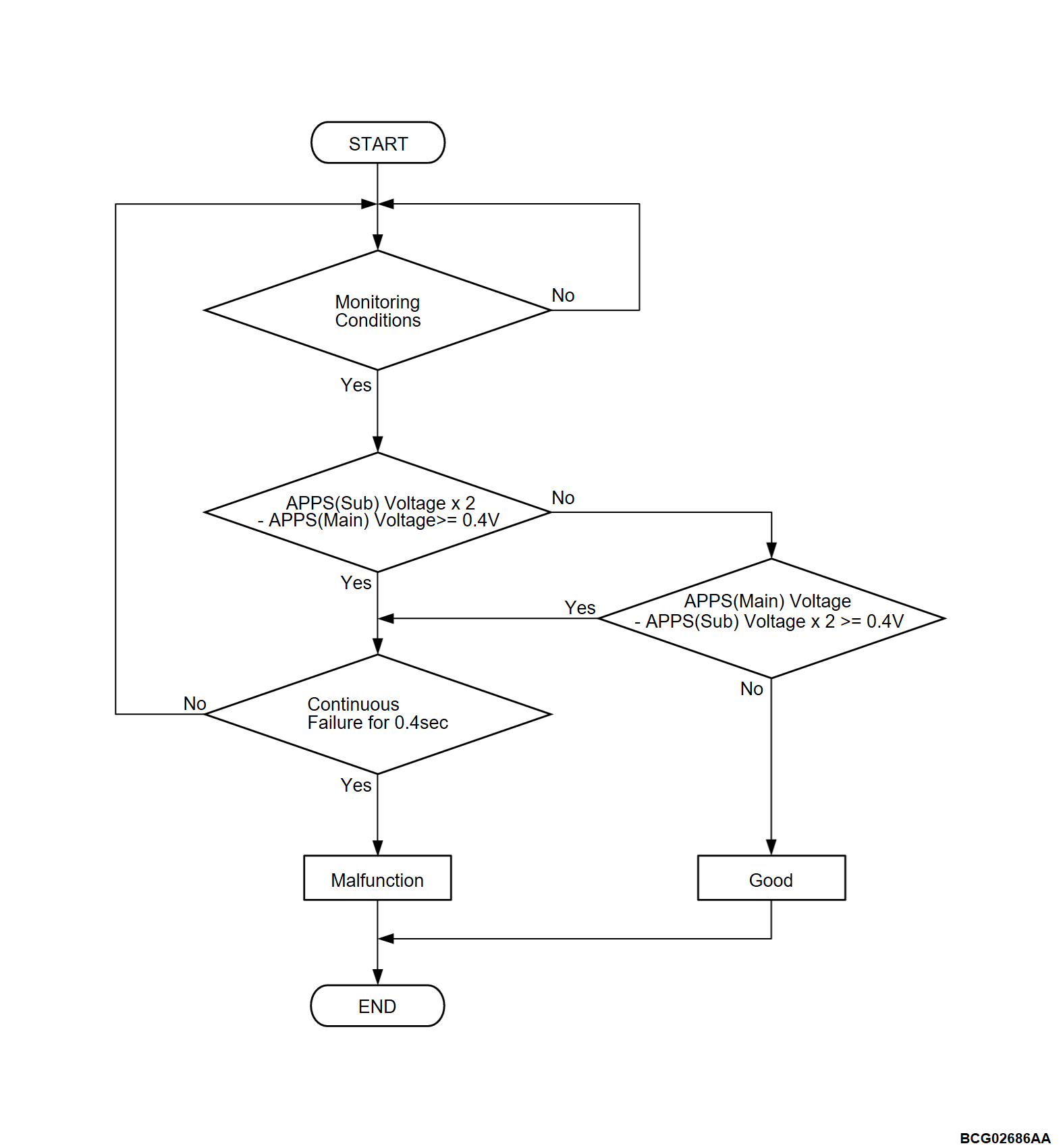
DTC P2138: APP sensor(main/sub) correlation
| caution | Before replacing the ECU, ensure that the communication circuit is normal. |
MONITOR EXECUTION
- Continuous
MONITOR EXECUTION CONDITIONS (Other monitor and Sensor)
Other Monitor (There is no temporary DTC stored in memory for the item monitored below)
- Not applicable
Sensor (The sensor below is determined to be normal)
- Not applicable
DTC SET CONDITIONS
Check Conditions
- The PHEV-ECU power supply voltage is more than 9.0 volts.
- The power supply mode of electric motor switch is ON.
Judgment Criterion
- When a state with the difference between the value of twice the accelerator pedal position sensor (sub) output voltage and the value of the accelerator pedal position sensor (main) output voltage being 0.4 volts or more continues for 0.4 seconds
- When a state with the difference between the value of the accelerator pedal position sensor (main) output voltage and the value of twice the accelerator pedal position sensor (sub) output voltage being 0.4 volts or more continues for 0.4 seconds
PROBABLE CAUSES
- Damaged harness or connector.
- Malfunction of the accelerator pedal position sensor (main/sub).
- Malfunction of the PHEV-ECU.
DIAGNOSIS
Required Special Tools
- MB991223: Wiring harness set
- MB992006: Extra fine probe
STEP 1. Check the wiring harness for damage (accelerator pedal position sensor and the PHEV-ECU).
Check the wiring harness between accelerator pedal position sensor connector and the PHEV-ECU connector (terminal APP1, APS1, APN1).
Is the check result normal?
STEP 2. Check the wiring harness for damage (accelerator pedal position sensor and the PHEV-ECU).
Check the wiring harness between accelerator pedal position sensor connector and the PHEV-ECU connector (terminal APP2, APS2, APN2).
Is the check result normal?
STEP 3. Using scan tool (M.U.T.-IIISE), check the data list.
Check that the following data list display contents are normal (Refer to  ).
).
 ).
).Data list
- Item No.78: APS1 voltage
|
- Item No.79: APS2 voltage
|
Is the check result normal?
![[Previous]](../../../buttons/fprev.png)
![[Next]](../../../buttons/fnext.png)


