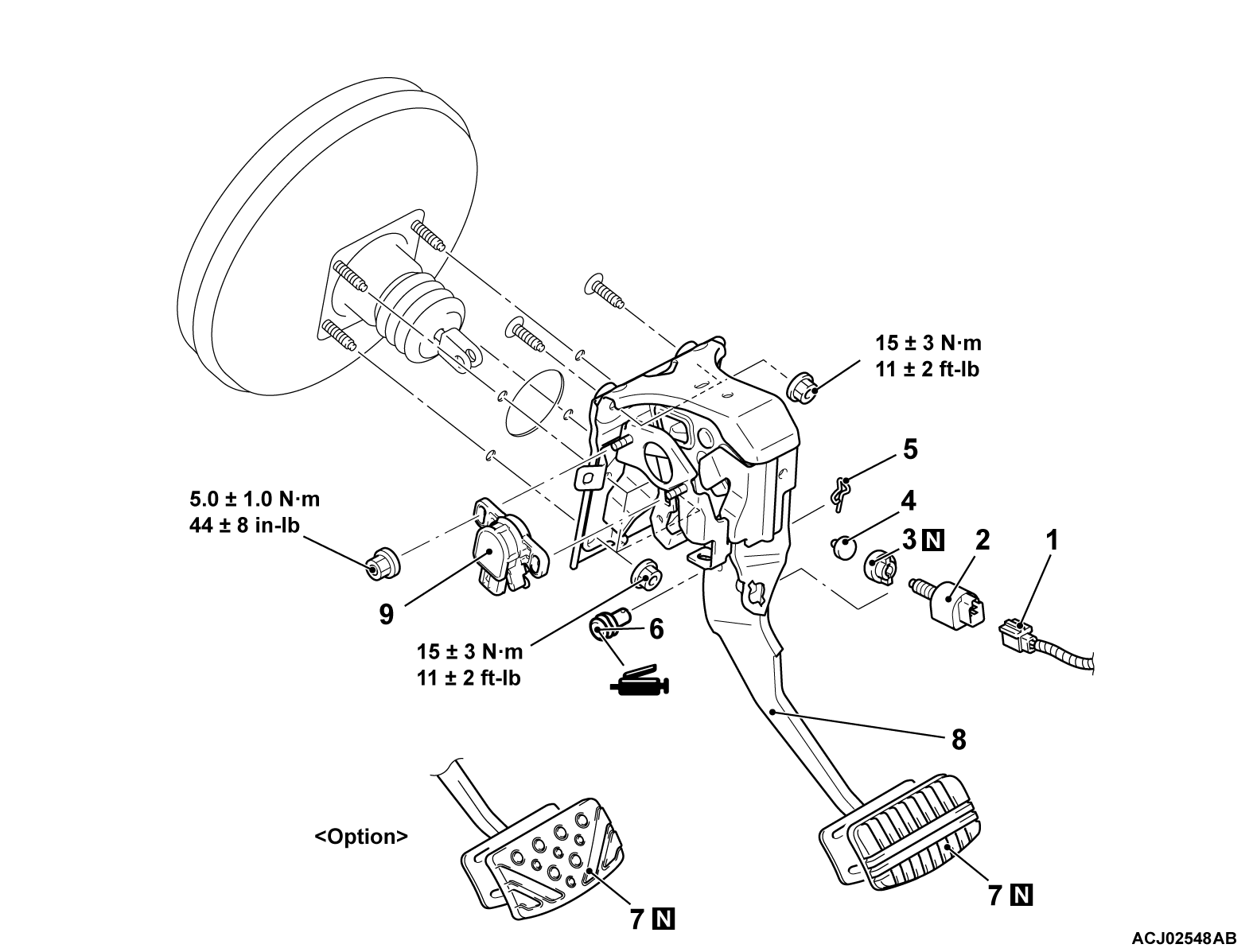
REMOVAL AND INSTALLATION
| caution |
|
REMOVAL SERVICE POINTS
<<A>> BRAKE PEDAL ASSEMBLY REMOVAL
1.
| caution | When placing the steering shaft assembly on the floor, be careful not to let the steering column lever contact the floor directly. |
Remove the steering shaft assembly mounting bolts, and place the steering shaft assembly on the floor with care not to let it contact the pedals and the seat.
2. From the engine compartment side, remove the brake pedal assembly while pulling the brake booster.
INSTALLATION SERVICE POINTS
>>A<< BRAKE PEDAL STROKE SENSOR INSTALLATION
1. <When reusing the sensor>
- Install the brake pedal stroke sensor to the brake pedal assembly temporarily.
- Install the brake pedal assembly.
caution - Before connecting or disconnecting the scan tool (M.U.T.-IIISE), turn off the power supply mode of the electric motor switch.
- While communicating with the scan tool (M.U.T.-IIISE), the power supply mode may not be turned ON by turning the power supply mode of the electric motor switch ON right after turning it OFF. If this happens, wait for several tens of seconds. Then, the power supply mode of the electric motor switch can be turned ON by operating the electric motor switch again.
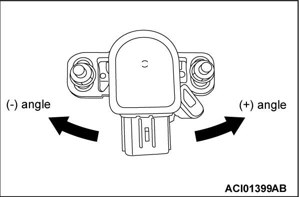
- Adjust the sensor position as shown, and tighten it to the specified torque while checking that the value of the PHEV-ECU data list (Item No. 85: B/P stroke sensor voltage) is within the normal value using the scan tool (M.U.T.-IIISE).
Normal value: 1.00 ± 0.12 volts
Tightening torque: 5.0 ± 1.0 N·m (44 ± 8 in - lb)
2. <When replacing with a new sensor>
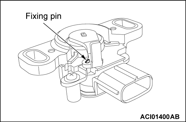
caution - Be careful not to break the fixing pin before installation.
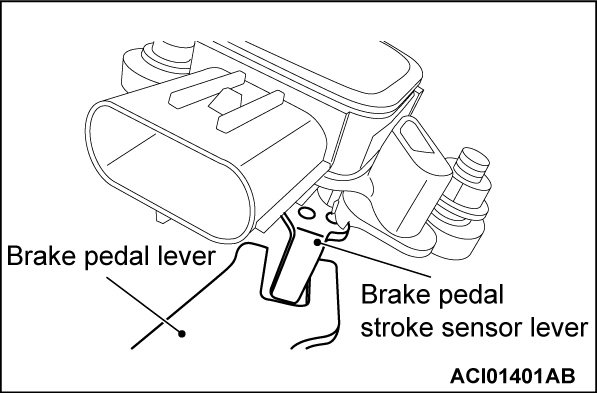
- Install the brake pedal stroke sensor while making sure that there is no clearance between the brake pedal stroke sensor lever and the brake pedal lever as shown, and tighten it to the specified torque.
- Install the brake pedal assembly.
caution - Before connecting or disconnecting the scan tool (M.U.T.-IIISE), turn off the power supply mode of the electric motor switch.
- While communicating with the scan tool (M.U.T.-IIISE), the power supply mode may not be turned ON by turning the power supply mode of the electric motor switch ON right after turning it OFF. If this happens, wait for several tens of seconds. Then, the power supply mode of the electric motor switch can be turned ON by operating the electric motor switch again.
- Using the scan tool (M.U.T.-IIISE), check that the value of the PHEV-ECU data list (Item No. 85: B/P stroke sensor voltage) is within the normal value.
caution Be sure to retrieve the broken fixing pin. - Using the scan tool (M.U.T.-IIISE), check that the brake pedal stroke sensor voltage is within the standard value.
- Depress the brake pedal and remove the fixing pin.
![[Previous]](../../../buttons/fprev.png)
![[Next]](../../../buttons/fnext.png)


