SERVICE MODE <VEHICLES WITH DISPLAY AUDIO (CD PLAYER EQUIPPED TYPE)>
HOW TO INITIATE THE SERVICE MODE
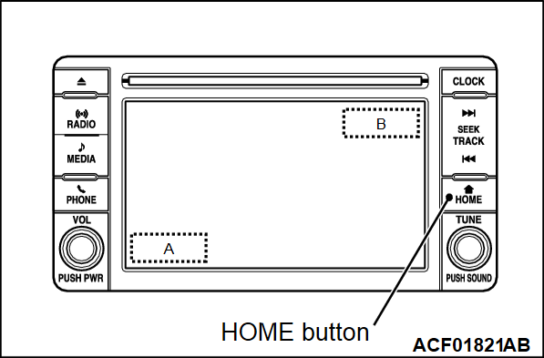
1. While pressing the "HOME" button, press "A" portion (shown in the illustration) on the display briefly. Then press "B" portion for at least two seconds.
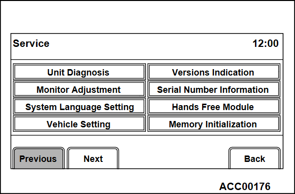
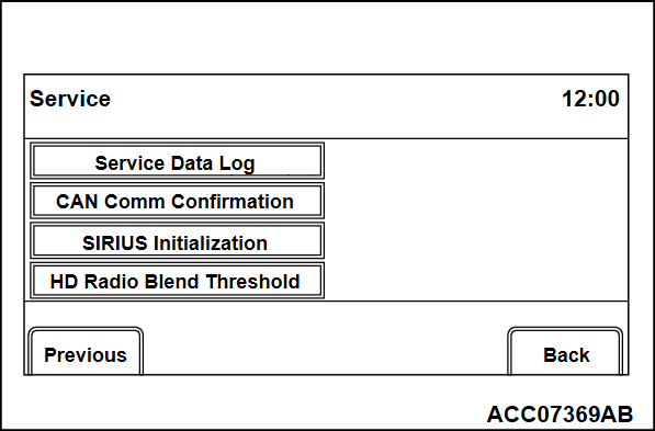
2. The service mode will be initiated. Then "Service" screen will be displayed.
HOW TO TERMINATE THE SERVICE MODE
If the operations below are done, the service mode will be terminated.
- If "Back" button is selected on "Service" screen, the service mode will terminate and then return to the previous screen.
SERVICE MODE ITEM
The following items can be checked or set in the service mode.
- Unit Diagnosis
- Monitor Adjustment
- System Language Setting
- Versions Indication
- Serial Number Information
- Hands Free Module
- Memory Initialization
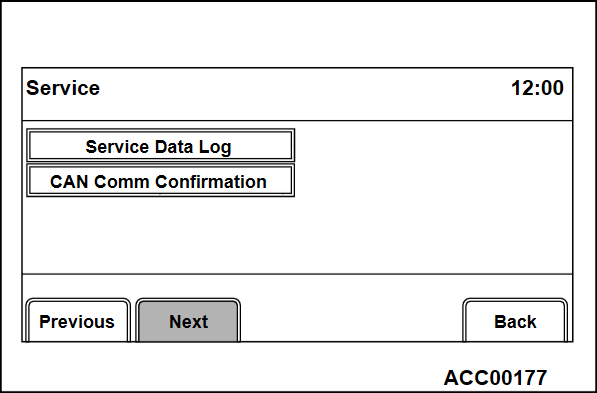
- Service Data Log
- CAN Comm Confirmation
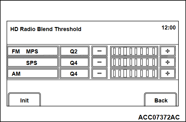
- HD Radio Blend Threshold
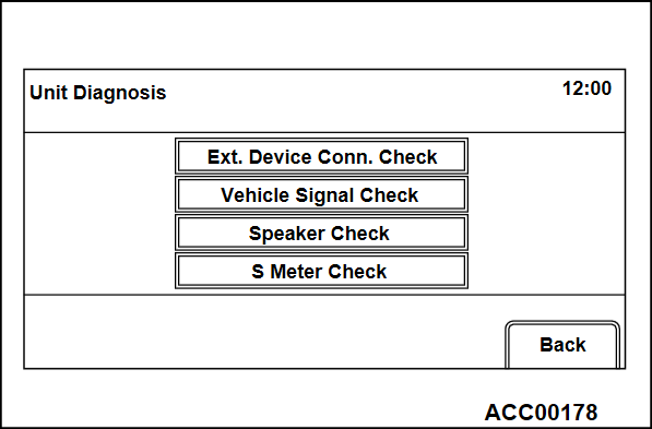
Unit Diagnosis
External Device Connection Check
1. Select "Ext. Device Conn. Check" button on "Unit Diagnosis" screen.
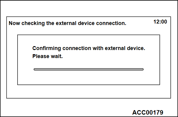
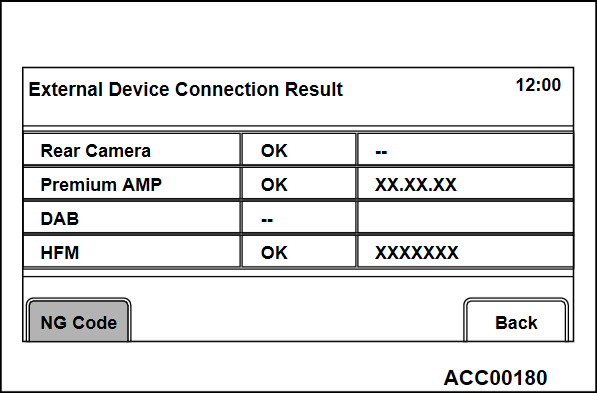
2. "Now checking the external device connection." will appear, and then it will switch to "External Device Connection Result" screen.
- If the connection with an equipment is detected, "OK" will be displayed.
- If the connection with an equipment is not detected, "--" will be displayed.
- In case other than above, "NG" is displayed.
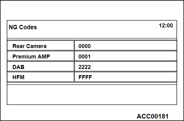
3. If "NG" is displayed on the check result screen, "NG code" will be displayed by pressing the respective button on "External Device Connection Result" screen.
| note | If "NG" is not displayed at all, "NG code" button is not active. |
Vehicle Signal Check
1. Select "Vehicle Signal Check" on "Unit Diagnosis" screen.
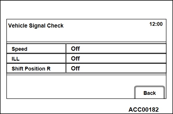
2. The current status of vehicle signal will be displayed.
- "Speed": "ON" when the vehicle speed is 6 km/h or more, and "OFF" when the vehicle speed is 4 km/h or less.
- "ILL": "ON" when the lighting switch is on (the taillights or the headlights are ON), and "OFF" when the taillights or the headlights are OFF.
- "Shift Position R": "ON" when the selector lever is at R position, and "OFF" when it is at the other position.
Speaker Check
1. Select "Speaker Check" button on "Unit Diagnosis" screen.
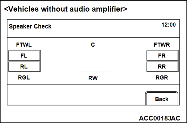
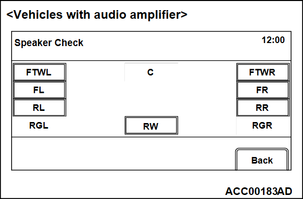
2. Select a speaker to be checked, and play test tone through the speaker.
<Vehicles without audio amplifier>
|
<Vehicles without audio amplifier>
| Screen display | The speaker which sounds a test tone |
| FL | Front door speaker (LH), front tweeter (LH) |
| FR | Front door speaker (RH), front tweeter (RH) |
| RL | Rear door speaker (LH) |
| RR | Rear door speaker (RH) |
<Vehicles with audio amplifier>
|
<Vehicles with audio amplifier>
| Screen display | The speaker which sounds a test tone |
| FL | Front door speaker (LH) |
| FR | Front door speaker (RH) |
| RL | Rear door speaker (LH) |
| RR | Rear door speaker (RH) |
| FTWL | Front tweeter (LH) |
| RTWR | Front tweeter (RH) |
| RW | Subwoofer |
| note |
|
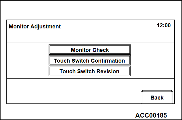
Monitor Adjustment
Monitor Check
1. Select "Monitor Check" button on "Monitor Adjustment" screen.
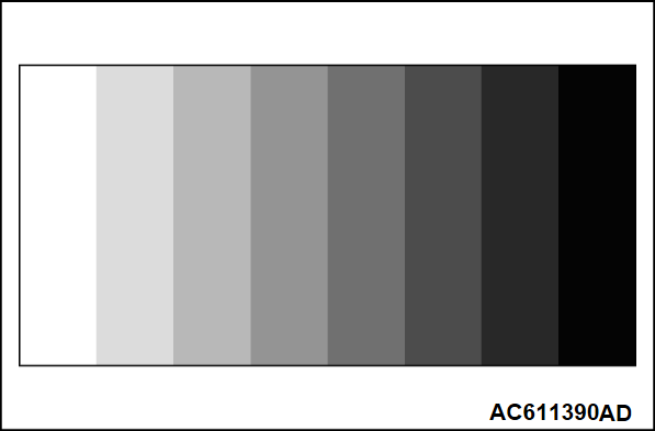
2. Eight color bars are displayed.
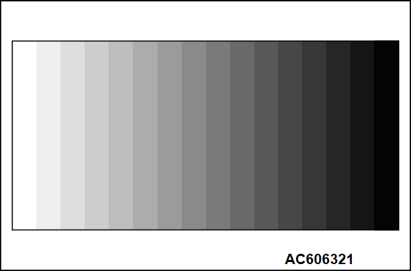
3. By touching the color bar screen, it will be switched to 16-gradient grayscale pattern.
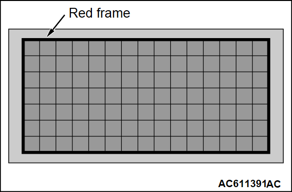
4. By touching the grayscale screen, it will be switched to a cross-hatch pattern. (Check whether the full-scale red frame is not misaligned)
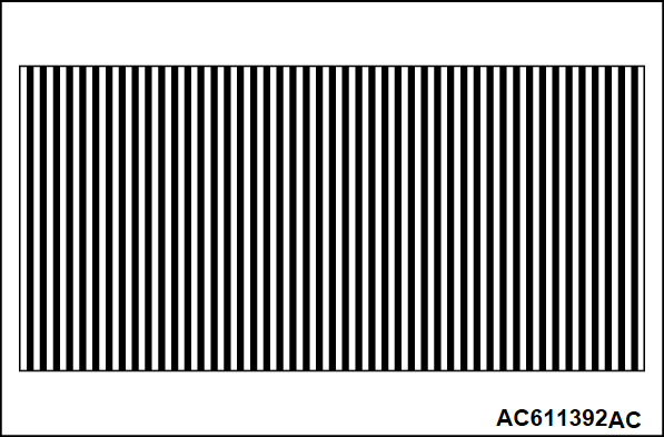
5. By touching the cross-hatch screen, it will be switched to a monocolor vertical stripe screen.
6. By touching the vertical stripe screen, it will be switched to a full-scale white screen.
7. By touching the full-scale white screen, it will be switched to a full-scale black screen.
8. By touching the full-scale black screen, it will be switched to a full-scale red screen.
9. By touching the full-scale red screen, it will be switched to a full-scale green screen.
10. By touching the full-scale green screen, it will be switched to a full-scale blue screen.
11. By touching the full-scale blue screen, it will be switched back to "Monitor Adjustment" screen.
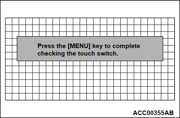
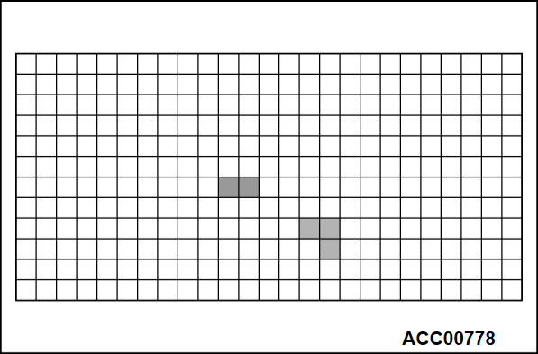
Touch Switch Confirmation
1. Select "Touch Switch Confirmation" button on "Monitor Adjustment" screen.
2. If you touch the screen, the color of the dotted coordinate at the touched area will be changed.
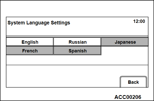
System Language Setting
1. Select "System Language Setting" button on "Service" screen.
2. Select your desired language. After a language is selected, it will be switched back to "Service" screen.
| note | After a "Back" button is selected, it will be also switched back to "Service" screen. |
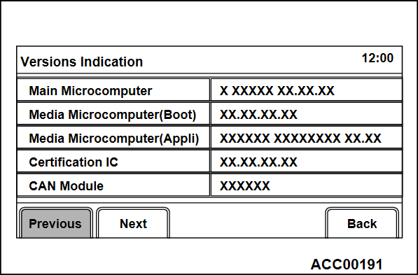
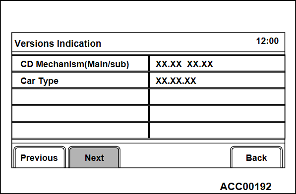
Versions Indication
1. Select "Versions Indication" button on "Service" screen.
2. A version information will be displayed.
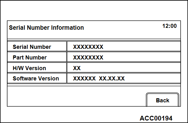
Serial Number Information
1. Select "Serial Number Information" button on "Service" screen.
2. A hardware identification number will be displayed.
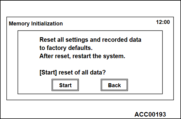
Memory Initialization
| caution | Executing "Memory Initialization" will erase the data stored by the customer. If you do so, it has only to be in agreement with the customer. |
1. Select "Memory Initialization" button on "Service" screen.
2. "Memory Initialization" screen will be displayed. When you select "Start" button, the initialization process will be executed.
| note | After a "Back" button is selected, it will be switched back to "Service" screen. |
3. After the memory initialization is successfully completed, the system will restart automatically.
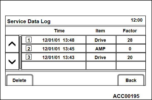
Service Data Log
1. Select "Service Data Log" button on "Service" screen.
2. The error log, which is stored during a system failure (drive failure), will be displayed.
| note |
|
EACH LOG INFORMATION: FACTOR CODE TABLE
|
EACH LOG INFORMATION: FACTOR CODE TABLE
| Item | Factor number | Produced log |
| Drive | 20 | Log concerning focus |
| 21 | Log concerning disc type | |
| 22 | Log concerning disc | |
| 25 | Log concerning SEEK | |
| 26 | Log concerning servo start-up | |
| 27 | Log concerning power-On | |
| 28 | Log concerning loading / eject operation | |
| 29 | Log concerning pick-up operation | |
| 30 | Log concerning state of mechanism | |
| 52 | Log concerning TOC reading | |
| HDD | 1 | Log concerning high temperature |
| 2 | Log concerning low temperature | |
| Monitor | 1 | Log concerning high temperature |
| AMP | 0 | Log concerning connection |
| 15 | Log concerning communication | |
| SP*1 | 1,2,8,15 | Log concerning number of speakers unexpected |
| CAR*2 | 0 -12, 130, 131, 160, 192, 255 | Log concerning vehicle model unexpected |
| note | *1: The log is displayed when the number of speakers is unexpected. *2: The log is displayed when the vehicle model is unexpected. |
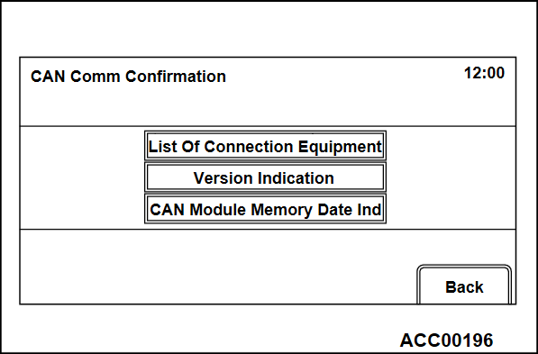
CAN Comm Confirmation
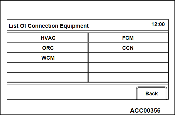
List Of Connection Equipment
1. Select "List Of Connection Equipment" button on "CAN Comm Confirmation" screen.
2. The system will search device(s), which are connected via CAN, and display the list of the devices.
List of connected devices
|
List of connected devices
| Screen indication | Equipment |
| HVAC | A/C-ECU |
| FCM | FCM/LDW/AHB-ECU |
| ORC | SRS-ECU |
| CCN | Combination meter |
| WCM | Wireless control module |
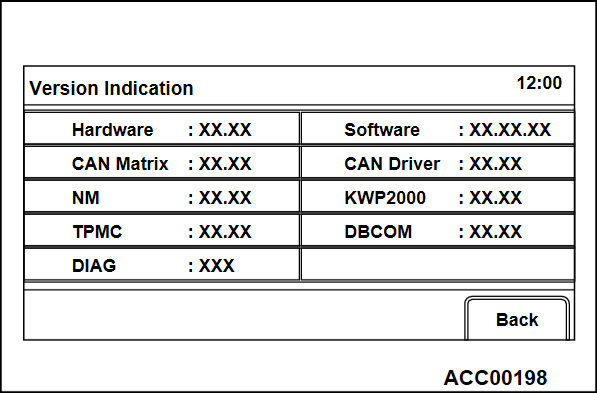
Version Indication
1. Select "Versions Indication" button on "CAN Comm Confirmation" screen.
2. A CAN version information will be displayed.
CAN Module Memory Data Indication
1. Select "CAN Module Memory Data Ind" button on "CAN Comm Confirmation" screen.
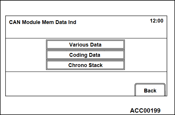
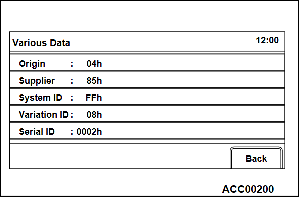
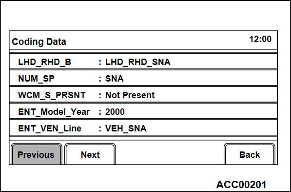
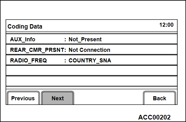
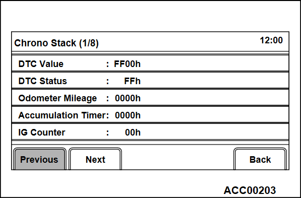
2. "CAN Module Memory Data Ind" will be displayed. A respective data will be displayed by selecting each button ("Various Data", "Coding data", "Chrono Stack").
- Select "Various Data."
- Select "Coding Data."
- Select "Chrono Stack."
![[Previous]](../../../buttons/fprev.png)
![[Next]](../../../buttons/fnext.png)
