CHECK OF ELECTRONIC CONTROL COUPLING
ELECTRONIC CONTROLLED COUPLING OPERATION CHECK
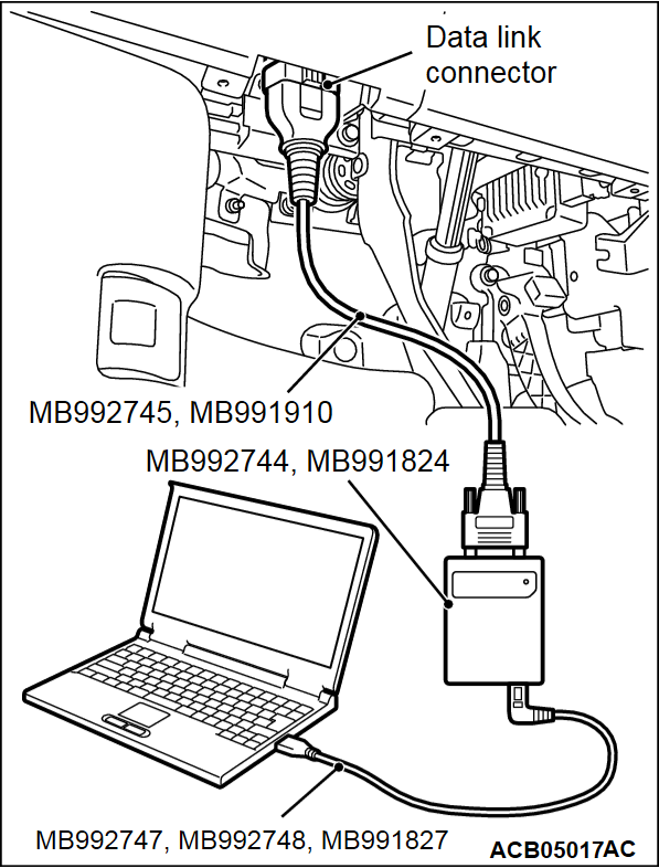
Required Special Tools:
- MB992744: Vehicle communication interface-Lite (V.C.I.-Lite)
- MB992745: V.C.I.-Lite main harness A
- MB992747: V.C.I.-Lite USB cable short
- MB992748: V.C.I.-Lite USB cable long
- MB991958: Scan Tool (M.U.T.-III Sub Assembly)
- MB991824: Vehicles Communication Interface (V.C.I.)
- MB991827: M.U.T.-III USB Cable
- MB991910: M.U.T.-III Main Harness A (Vehicles with CAN communication system)
1.
| caution | To prevent damage to scan tool (M.U.T.-III), always turn the ignition switch to the "LOCK" (OFF) position before connecting or disconnecting scan tool (M.U.T.-III). |
2. Start the engine.
3. Position the steering wheel in a straight ahead direction.
4. Execute "Test" (item No. 6 Center coupling operation check) on scan tool (M.U.T.-III) special function to activate the electronic-controlled coupling.
| note |
|
5. Turn the steering wheel 360° or more clockwise or counterclockwise, move the selector lever to the D range (1st), and start the vehicle slowly. The vehicle should hesitate to move. This phenomenon is called as "tight corner braking".
| note |
|
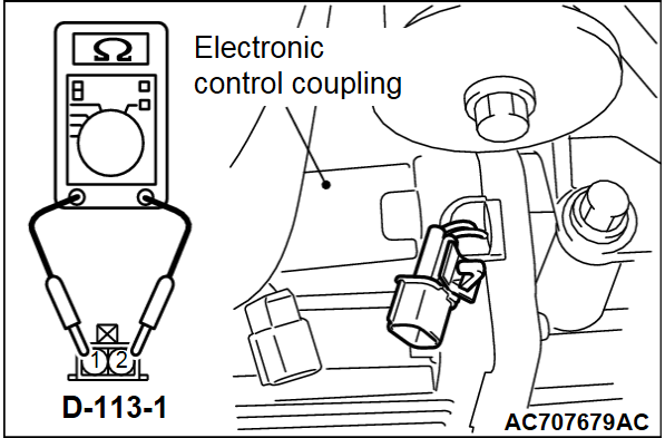
RESISTANCE MEASUREMENT BETWEEN ELECTRONIC CONTROL COUPLING SOLENOID CONNECTOR TERMINALS
Disconnect the electronic control coupling solenoid connector, and measure the resistance value between the connector terminals on the unit side. If the measured resistance value is out of the standard value range, replace the electronic control coupling (Refer to  ).
).
 ).
).Standard value: 2.2 - 4.0 Ω
![[Previous]](../../../buttons/fprev.png)
![[Next]](../../../buttons/fnext.png)

