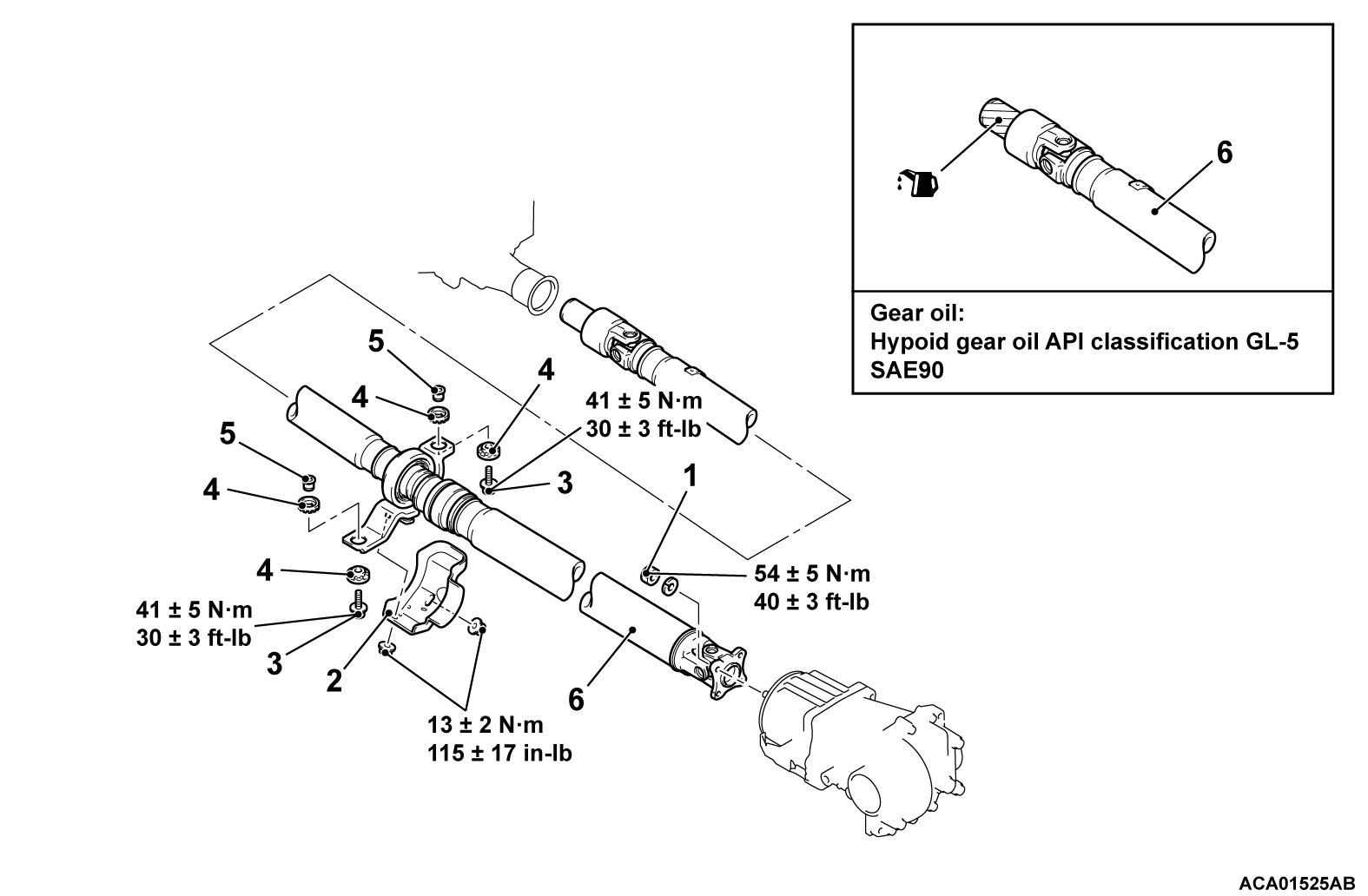
REMOVAL AND INSTALLATION
Pre-removal and Post-installation operation |
Required Special Tool:
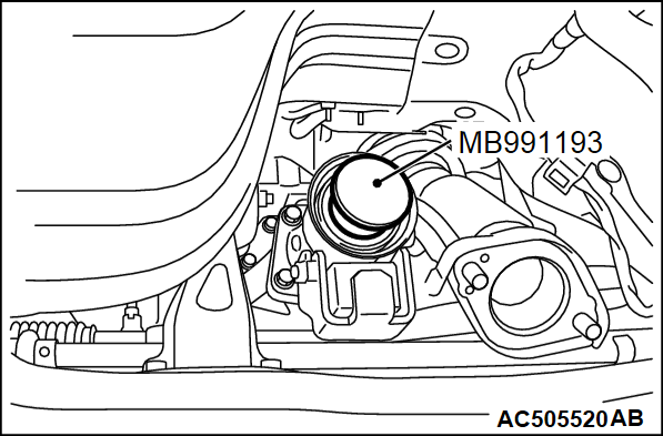
- MB991193: Plug
REMOVAL SERVICE POINTS
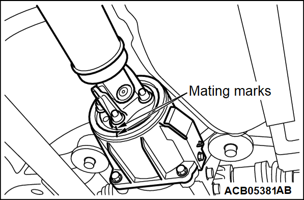
<<A>> FLANGE YOKE AND ELECTRONIC CONTROL COUPLING CONNECTING NUT REMOVAL
Put mating marks on the flange yoke and the electronic control coupling.
<<B>> PROPELLER SHAFT ASSEMBLY REMOVAL
1.
Insert a waste or similar materials into the joint boots, and remove the propeller shaft assembly by aligning the front propeller shaft with the rear shaft.
| caution | If the joint assembly is bent, it may be damaged when pinching the joint boots. |
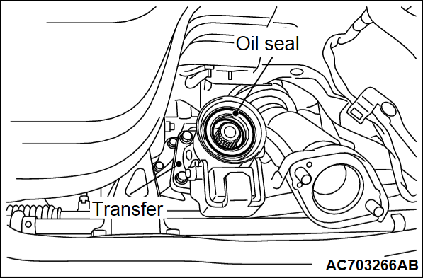
2. Using special tool plug (MB991193), cover the transfer case to prevent the entry of foreign materials.
INSTALLATION SERVICE POINT
>>A<< PROPELLER SHAFT ASSEMBLY INSTALLATION
| caution |
|
>>B<< FLANGE YOKE AND ELECTRONIC CONTROL COUPLING CONNECTING NUT INSTALLATION
If the propeller shaft is reused, align the mating marks and install the connecting nuts.
Tightening torque: 54 ± 5 N·m (40 ± 3 ft-lb)
![[Previous]](../../../buttons/fprev.png)
![[Next]](../../../buttons/fnext.png)


