REMOVAL AND INSTALLATION <2.4L ENGINE>
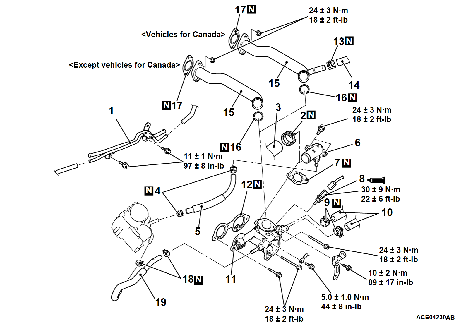
Pre-removal Operation | Post-installation Operation |
Required Special Tools:
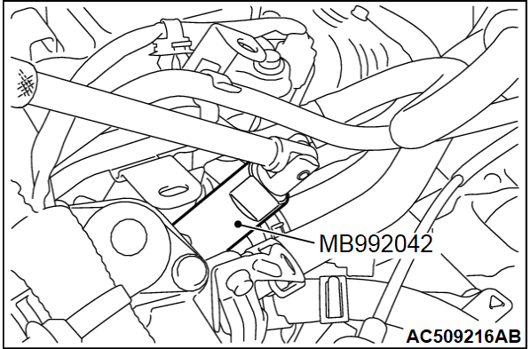
- MB992042: Water Temperature Sensor Wrench
REMOVAL SERVICE POINTS
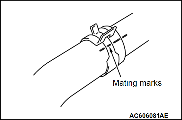
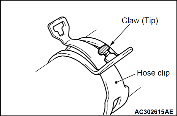
<<A>> HOSE CLIPS/HOSES DISCONNECTION
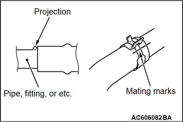
1. Make mating marks on the hoses and hose clips as shown to install them in the original position. Then, remove them.
2. Break off the tip of hose clip claw and spread out the hose clip, then disconnect the hose.
| note | If there is a hose clip claw, the hose clip cannot spread to capacity because the claw contacts the hose clip. |
INSTALLATION SERVICE POINTS
>>A<< HOSE CLIPS/HOSES CONNECTION
1. Insert hose as far as the projection of the water outlet fitting.
2. Align the mating marks on the hoses and hose clips, and then connect the hoses.
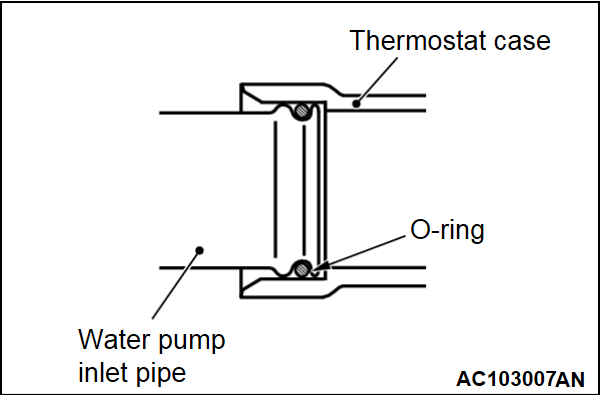
>>B<< O-RING INSTALLATION
| caution | Avoid adhesion of engine oil or grease to the O-ring. |
Fit the O-ring in the water inlet pipe groove, wet the O-ring circumference or the pipe mounting area inner wall, and then insert the O-ring.
>>C<< ENGINE COOLANT TEMPERATURE SENSOR INSTALLATION
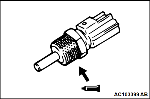
1. Apply the specified sealant to the engine coolant temperature sensor thread.
Specified sealant: ThreeBond 1324N or equivalent
| note | Install the engine coolant temperature sensor immediately after applying sealant. |
2.
Use special tool water temp sensor wrench (MB992042) to tighten the engine coolant temperature sensor to the specified torque.
| caution | After the installation, until a sufficient period of time (one hour or more) elapses, do not apply the engine oil or water to the sealant application area or start the engine. |
Tightening torque: 30 ± 9 N·m (22 ± 6 ft-lb)
![[Previous]](../../../buttons/fprev.png)
![[Next]](../../../buttons/fnext.png)

