DTC P2138: Accelerator Pedal Position Sensor (main and sub) Range/Performance Problem
ACCELERATOR PEDAL POSITION SENSOR (MAIN AND SUB) RANGE/PERFORMANCE CIRCUIT
CIRCUIT OPERATION
TECHNICAL DESCRIPTION
- ECM checks the accelerator pedal position sensor output signal characteristics for abnormal conditions.
DESCRIPTIONS OF MONITOR METHODS
- Detect malfunction if the relation between accelerator pedal position sensor (main) and accelerator pedal position sensor (sub) is wrong.
MONITOR EXECUTION
- Continuous
MONITOR EXECUTION CONDITIONS (Other monitor and Sensor)
Other Monitor (There is no temporary DTC set in memory for the item monitored below)
- Not applicable
Sensor (The sensor below is determined to be normal)
- Not applicable
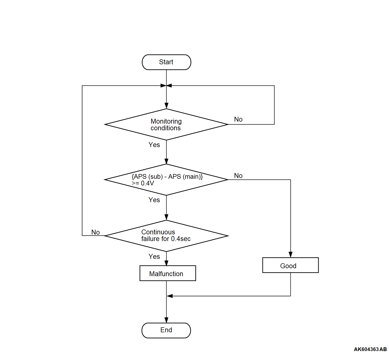
Check Condition
- Change of accelerator pedal position sensor (sub) output voltage per 25 milliseconds is lower than 0.06 volt.
Judgment Criterion
- The accelerator pedal position sensor (main) output voltage subtracted from the accelerator pedal position sensor (sub) output voltage is more than 0.4 volt for 0.4 second.
note The accelerator pedal position sensor voltage used for the judgment is converted into the accelerator pedal position sensor voltage for the internal processing by the ECM.
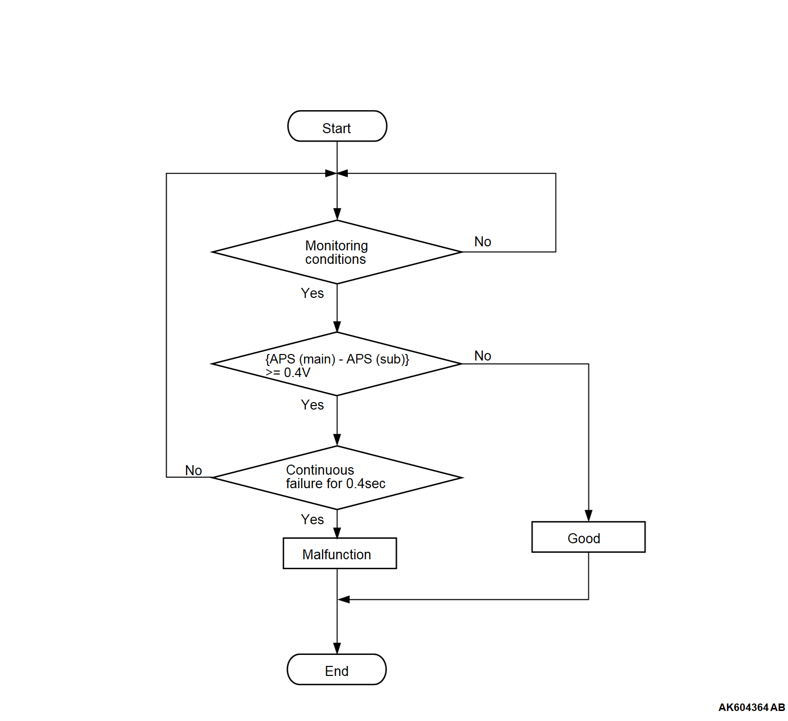
Check Condition
- Change of accelerator pedal position sensor (sub) output voltage per 25 milliseconds is lower than 0.06 volt.
Judgment Criterion
- The accelerator pedal position sensor (sub) output voltage subtracted from the accelerator pedal position sensor (main) output voltage is more than 0.4 volt for 0.4 second.
note The accelerator pedal position sensor voltage used for the judgment is converted into the accelerator pedal position sensor voltage for the internal processing by the ECM.
FAIL-SAFE AND BACKUP FUNCTION
- Throttle opening degree is restricted.
- Throttle opening degree position is in default position if accelerator pedal position sensor (sub) fails.
OBD-II DRIVE CYCLE PATTERN
- None
TROUBLESHOOTING HINTS (The most likely causes for this code to be set are:)
- Accelerator pedal position sensor failed.
- Connector damage.
- Harness damage.
- ECM failed.
DIAGNOSIS
Required Special Tools:
- MB992744: Vehicle communication interface-Lite (V.C.I.-Lite)
- MB992745: V.C.I.-Lite main harness A
- MB992747: V.C.I.-Lite USB cable short
- MB992748: V.C.I.-Lite USB cable long
- MB991958: Scan Tool (M.U.T.-III Sub Assembly)
- MB991824: Vehicles Communication Interface (V.C.I.)
- MB991827: M.U.T.-III USB Cable
- MB991910: M.U.T.-III Main Harness A (Vehicles with CAN communication system)
STEP 1. Using scan tool (M.U.T.-III), check data list item 11: Accelerator Pedal Position Sensor (main).
| caution | To prevent damage to scan tool (M.U.T.-III), always turn the ignition switch to the "LOCK" (OFF) position before connecting or disconnecting scan tool (M.U.T.-III). |
(2) Turn the ignition switch to the "ON" position.
(3) Set scan tool (M.U.T.-III) to the data reading mode for item 11, Accelerator Pedal Position Sensor (main).
- Output voltage should be between 0.9 and 1.1 volts when foot is released from accelerator pedal.
- Output voltage should be 4.0 volts or higher when accelerator pedal is fully depressed.
(4) Turn the ignition switch to the "LOCK" (OFF) position.
Is the sensor operating properly?
STEP 2. Using scan tool (M.U.T.-III), check data list item 12: Accelerator Pedal Position Sensor (sub).
(1) Turn the ignition switch to the "ON" position.
(2) Set scan tool (M.U.T.-III) to the data reading mode for item 12, Accelerator Pedal Position Sensor (sub).
- Output voltage should be between 0.4 and 0.6 volts when foot is released from accelerator pedal.
- Output voltage should be 2.0 volts or higher when accelerator pedal is fully depressed.
(3) Turn the ignition switch to the "LOCK" (OFF) position.
Is the sensor operating properly?
STEP 3. Check the continuity at accelerator pedal position sensor harness side connector.
(1) Disconnect the accelerator pedal position sensor connector and measure at the harness side.
(2) Check for the continuity between terminal APSE line and ground.
- Continuity (2 ohms or less)
Does continuity exist?
STEP 4. Check of harness damage in APSE line between accelerator pedal position sensor connector and ECM connector.
Is the harness wire in good condition?
STEP 5. Check the continuity at accelerator pedal position sensor harness side connector.
(1) Disconnect the accelerator pedal position sensor connector and measure at the harness side.
(2) Check for the continuity between terminal EV line and ground.
- Continuity (2 ohms or less)
Does continuity exist?
STEP 6. Check of harness damage in EV line between accelerator pedal position sensor connector and ECM connector.
Is the harness wire in good condition?
STEP 7. Using scan tool (M.U.T.-III), read the diagnostic trouble code (DTC).
(1) Turn the ignition switch to the "ON" position.
(2) After the DTC has been deleted, read the DTC again.
(3) Turn the ignition switch to the "LOCK" (OFF) position.
Is DTC P2138 set?
STEP 8. Check of harness damage in APS5 line between accelerator pedal position sensor connector and ECM connector.
Is the harness wire in good condition?
STEP 9. Check of harness damage in 5VV line between accelerator pedal position sensor connector and ECM connector.
Is the harness wire in good condition?
STEP 10. Check of harness damage in APSM line between accelerator pedal position sensor connector and ECM connector.
Is the harness wire in good condition?
STEP 11. Check of harness damage in APSS line between accelerator pedal position sensor connector and ECM connector.
Is the harness wire in good condition?
STEP 12. Replace the accelerator pedal assembly.
(1) Replace the accelerator pedal assembly.
(2) Turn the ignition switch to the "ON" position.
(3) After the DTC has been deleted, read the DTC again.
(4) Turn the ignition switch to the "LOCK" (OFF) position.
Is DTC P2138 set?
 The inspection is complete.
STEP 13. Using scan tool (M.U.T.-III), read the diagnostic trouble code (DTC).
(1) Turn the ignition switch to the "ON" position.
(2) After the DTC has been deleted, read the DTC again.
(3) Turn the ignition switch to the "LOCK" (OFF) position.
Is DTC P2138 set?
 Retry the troubleshooting.
 The inspection is complete.
![[Previous]](../../../buttons/fprev.png)
![[Next]](../../../buttons/fnext.png)


