DTC P014F: Linear Air-Fuel Ratio Sensor Circuit Slow Response - Lean to Rich (bank 2, sensor 1)
TECHNICAL DESCRIPTION
- The ECM effects air/fuel ratio feedback control in accordance with the signals from the left bank linear air-fuel ratio sensor.
- If the left bank linear air-fuel ratio sensor has deteriorated, corrections will be made by the heated oxygen sensor (rear).
DESCRIPTIONS OF MONITOR METHODS
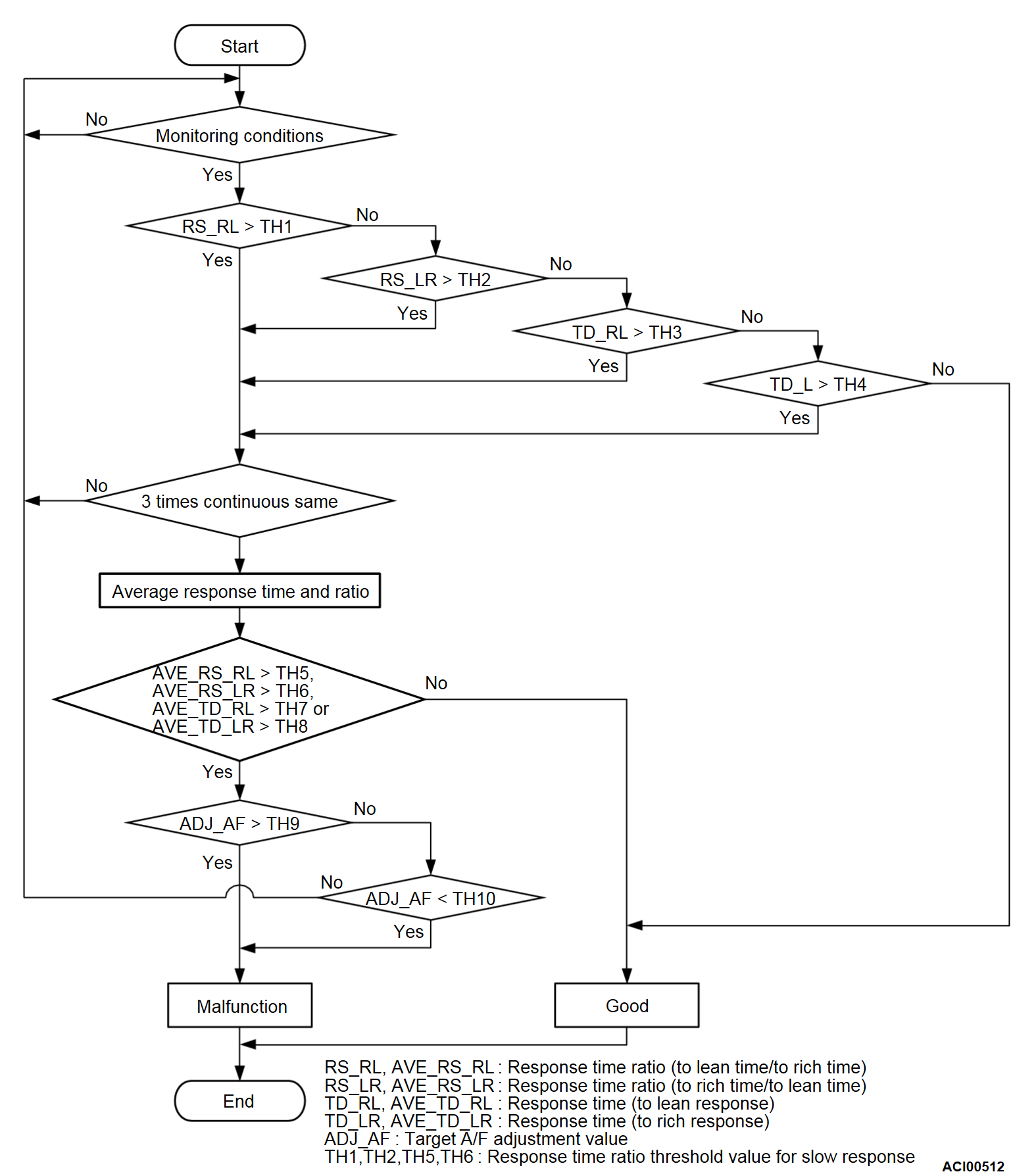
- When the average of the difference between the response times of the rich side and the lean side of the left bank linear air-fuel ratio sensor during the monitoring time becomes equal to or higher than the predetermined value, the DTC is set as the left bank linear air-fuel ratio sensor deterioration.
MONITOR EXECUTION
- Continuous
MONITOR EXECUTION CONDITIONS (Other monitor and Sensor)
Other Monitor (There is no temporary DTC set in memory for the item monitored below)
- Left bank linear air-fuel ratio sensor heater monitor
- Misfire monitor
- Fuel system monitor
Sensor (The sensor below is determined to be normal)
- Mass airflow sensor
- Engine coolant temperature sensor
- Intake air temperature sensor
- Barometric pressure sensor
- Throttle position sensor
- Accelerator pedal position sensor
Check Conditions
- Engine speed is between 1,188 and 3,000 r/min.
- Volumetric efficiency is between 21.8 and 68.8 percent.
- Mass airflow sensor output is 8 g/sec or more.
- Engine coolant temperature is more than 60°C (140°F).
- Under the closed loop air/fuel control.
- The accelerator pedal is depressed.
- Short-term fuel trim is between -25 and +25 percent.
- More than 3 seconds have passed after the above mentioned conditions have been met.
- Left bank linear air-fuel ratio sensor signal length is 2.50 or less.
- During the drive cycle, the ECM performs monitoring with the accumulated total time of 10 seconds, 3 times.
Judgment Criteria
- The average response time ratio (to rich time/to lean time) is more than specified value.
- The amount of compensated air/fuel ratio based on the heated oxygen sensor (rear) is out of specified amount.
FAIL-SAFE AND BACKUP FUNCTION
- None
TROUBLESHOOTING HINTS (The most likely causes for this code to be set are:)
- Left bank linear air-fuel ratio sensor failed.
DIAGNOSIS
Required Special Tools:
- MB992744: Vehicle Communication Interface-Lite (V.C.I.-Lite)
- MB992745: V.C.I.-Lite Main Harness A
- MB992747: V.C.I.-Lite USB Cable Short
- MB992748: V.C.I.-Lite USB Cable Long
- MB991958: Scan Tool (M.U.T.-III Sub Assembly)
- MB991824: Vehicles Communication Interface (V.C.I.)
- MB991827: M.U.T.-III USB Cable
- MB991910: M.U.T.-III Main Harness A (Vehicles with CAN communication system)
STEP 1. Test the OBD-II drive cycle.
| caution | To prevent damage to scan tool (M.U.T.-III), always turn the ignition switch to the "LOCK" (OFF) position before connecting or disconnecting scan tool (M.U.T.-III). |
(2) Turn the ignition switch to the "ON" position and delete the DTC.
(3) Carry out the test drive with the drive cycle pattern. Refer to Diagnostic Function - OBD-II Drive Cycle - Pattern 1  .
.
 .
.(4) Check the diagnostic trouble code (DTC).
Is DTC P014F set?
![[Previous]](../../../buttons/fprev.png)
![[Next]](../../../buttons/fnext.png)


