COMPRESSION PRESSURE CHECK
Required Special Tools:
- MB992744: Vehicle communication interface-Lite (V.C.I.-Lite)
- MB992745: V.C.I.-Lite main harness A
- MB992747: V.C.I.-Lite USB cable short
- MB992748: V.C.I.-Lite USB cable long
- MB991958: Scan Tool (M.U.T.-III Sub Assembly)
- MB991824: Vehicles Communication Interface (V.C.I.)
- MB991827: M.U.T.-III USB Cable
- MB991910: M.U.T.-III Main Harness A (Vehicles with CAN communication system)
1. Before inspection, check that the engine oil, starter and battery are normal. Also, set the vehicle to the pre-inspection condition.
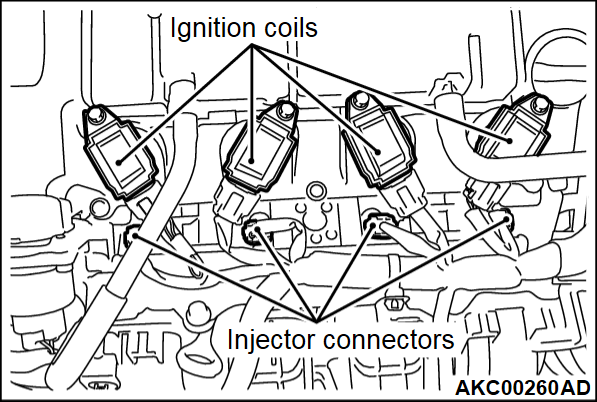
2. Remove all of the ignition coils and spark plugs. (Refer to GROUP 11B - Generator and Ignition System  ).
).
 ).
).3. Disconnect the all of the injector connectors.
| warning | Keep your distance from the spark plug hole when cranking. Oil, fuel, etc., may spray out from the spark plug hole and may cause serious injury. |
4. Cover the spark plug hole with a shop towel etc., after the engine has been cranked, check that no foreign material is adhering to the shop towel.
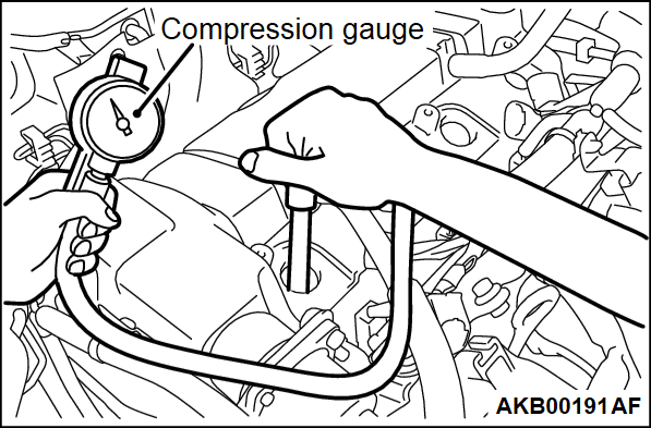
5. Set compression gauge to one of the spark plug holes.
6. Cranking the engine with the accelerator pedal fully depressed, measure the compression pressure.
- Standard value (at engine speed of 200 r/min): 1,180 kPa (171 psi)
- Limit (at engine speed of 200 r/min): Minimum 800 kPa (116 psi)
7. Measure the compression pressure for all the cylinders, and check that the pressure differences of the cylinders are below the limit.
Limit: Maximum 150 kPa (22 psi)
8. If there is a cylinder with compression or a compression difference that is outside the limit, pour a small amount of engine oil through the spark plug hole, and repeat the operations in steps from 5 to 7.
(1) If the compression increases after oil is added, the cause of the malfunction is a worn or damaged piston ring and/or cylinder inner surface.
(2) If the compression does not rise after oil is added, the cause is a burnt or defective valve seat, or pressure is leaking from the gasket.
9. Connect the all of the injector connector.
10. Install all of the spark plugs and ignition coils. (Refer to GROUP 11B - Generator and Ignition System  ).
).
 ).
).11.
| caution | To prevent damage to scan tool (M.U.T.-III), always turn the ignition switch to the "LOCK" (OFF) position before connecting or disconnecting scan tool (M.U.T.-III). |
![[Previous]](../../../buttons/fprev.png)
![[Next]](../../../buttons/fnext.png)

