Inspection Procedure 3: ECALL speaker/front door speaker (RH) does not sound.
| caution | When replacing the ECU, always check that the communication circuit is normal. |
TECHNICAL DESCRIPTION (COMMENT)
If the ECALL speaker and the front door speaker (RH) do not sound, there is a possibility that a defect in the ECALL speaker, a defect in the front door speaker (RH), a defect in the ECALL relay box assembly or a defect in the TCU.
TROUBLESHOOTING HINTS
- The wiring harness or connectors may have loose, corroded, or damaged terminals, or terminals pushed back in the connector
- The ECALL speaker may be defective
- The front door speaker (RH) may be defective
- The ECALL relay box assembly may be defective
- The TCU may be defective
DIAGNOSIS
Required Special Tools:
- MB991223: Harness Set
- MB992006: Extra Fine Probe
STEP 1. Using scan tool (M.U.T.-IIISE), check the special Function.
Using scan tool (M.U.T.-IIISE), select "Test" from the special function of the TCU.
(1)
| caution | To prevent damage to scan tool (M.U.T.-IIISE), always turn the ignition switch to the "LOCK" (OFF) position before connecting or disconnecting scan tool (M.U.T.-IIISE). |
- Item 2: Emergency speaker check (Beep)
- Item 4: Door speaker check (Beep)
Is the check result normal?
STEP 2. Check ECALL speaker.
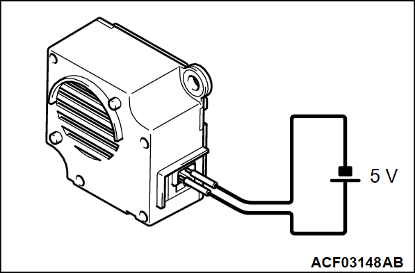
(2) Check that the ECALL speaker outputs the noise when the voltage of 5 volts is applied to the ECALL speaker connector terminal.
Do the ECALL speaker output the noise?
STEP 3. Resistance measurement at the ECALL relay box assembly connector (ESO-, ESO+ terminals).
(1) Disconnect the ECALL relay box assembly connector, and measure at the wiring harness side.
(2) Check the resistance between the ECALL relay box assembly connector (ESO- terminal) and (ESO+ terminal).
OK: 1.5 - 70 ohms
(3) Check the resistance between the ECALL relay box assembly connector (ESO+ terminal) and body ground.
OK: No continuity
Is the check result normal?
 Repair the connector(s) or wiring harness.
STEP 4. Voltage measurement at the ECALL relay box assembly connector (IG, GND terminals).
(1) Disconnect the ECALL relay box assembly connector, and measure at the wiring harness side.
(2) Turn the ignition switch from OFF position to ON position.
(3) Check the voltage between the ECALL relay box assembly connector (IG terminal) and (GND terminal).
OK: The voltage should measure approximately 12 volts (battery positive voltage).
Is the check result normal?
 Correct the IG line circuit or GND circuit of the ECALL relay box assembly.
STEP 5. Check front door speaker (RH).
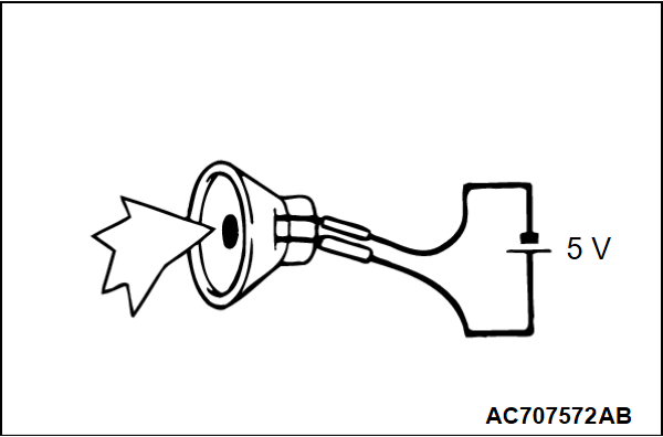
(2) Check that the ECALL speaker outputs the noise when the voltage of 5 volts is applied to the ECALL speaker connector terminal.
Do the front door speaker (RH) output the noise?
STEP 6. Resistance measurement at the ECALL relay box assembly connector (terminals No. 11, 12).
(1) Disconnect the ECALL relay box assembly connector, and measure at the wiring harness side.
(2) Check the resistance between the ECALL relay box assembly connector (DSO+ terminal) and (DSO- terminal).
OK: 1.5 - 70 ohms
(3) Check the resistance between the ECALL relay box assembly connector (DSO+ terminal) and body ground.
OK: No continuity
Is the check result normal?
 Repair the connector(s) or wiring harness.
STEP 7. Voltage measurement at the ECALL relay box assembly connector (RLE1, RLE2 terminals).
(1) Disconnect the ECALL relay box assembly connector, and measure at the wiring harness side.
(2) Turn the ignition switch from OFF position to ON position.
(3)
| caution | Execute item No. 4 "Door speaker check (Beep)" in the scan tool (M.U.T.-IIISE) special function "Test", and measure the voltage. |
Check the voltage between the ECALL relay box assembly connector (RLE1 terminal) and body ground.
OK: Approximately 5 volts
(4) Check the voltage between the ECALL relay box assembly connector (RLE2 terminal) and body ground.
OK: Approximately 5 volts
Is the check result normal?
STEP 8. Resistance measurement at the TCU connector (SPO+, SPO- terminals).
(1) Disconnect the TCU connector, and measure at the wiring harness side.
(2) Check the resistance between the TCU connector (SPO+ terminal) and (SPO- terminal).
OK: 1.5 - 70 ohms
(3) Check the resistance between the TCU connector (SPO+ terminal) and body ground.
OK: No continuity
Is the check result normal?
STEP 9. Resistance measurement at the TCU connector (SPO+, SPO- terminals).
(1) Disconnect the TCU connector and the ECALL relay box assembly connector, and measure at the wiring harness side.
(2) Check the resistance between the TCU connector (SPO+ terminal) and the ECALL relay box assembly connector (ESI+ terminal).
OK: The resistance should be 2 ohms or less
(3) Check the resistance between the TCU connector (SPO- terminal) and the ECALL relay box assembly connector (ESI- terminal).
OK: The resistance should be 2 ohms or less
(4) Check the resistance between the TCU connector (SPO+ terminal) and body ground.
OK: No continuity
(5) Check the resistance between the TCU connector (SPO- terminal) and body ground.
OK: No continuity
Is the check result normal?
 Repair the connector(s) or wiring harness.
![[Previous]](../../../buttons/fprev.png)
![[Next]](../../../buttons/fnext.png)


