INSPECTION
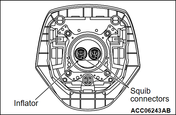
DRIVER'S AIR BAG MODULE
| danger | Never attempt to measure the circuit resistance of the air bag modules (squib), even if you are using the specified tester. If the circuit resistance is measured with a tester, accidental air bag deployment will result, and possible serious personal injury. |
| warning | If any component damage is found during the following inspection, replace the air bag module with a new one. Dispose of the old one according to the specified procedure (Refer to  ). ). |
If any malfunction is found in the following inspections, replace the air bag module with a new one.
1. Check the pad cover for dents, crack or deformation.
2. Check the harness and connector for damage and the terminal for deformation.
3. Check the air bag inflator cases for dents, cracks or deformation.
4. Check the air bag module for proper installation.
CLOCK SPRING
If any malfunction is found in the following inspections, replace the clock spring with a new one.
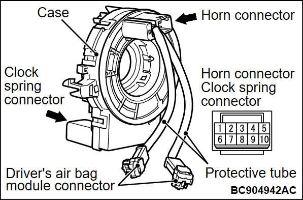
1. Check the connectors and protective tubes for damage and the terminal for deformation.
2. Check the case for damage.
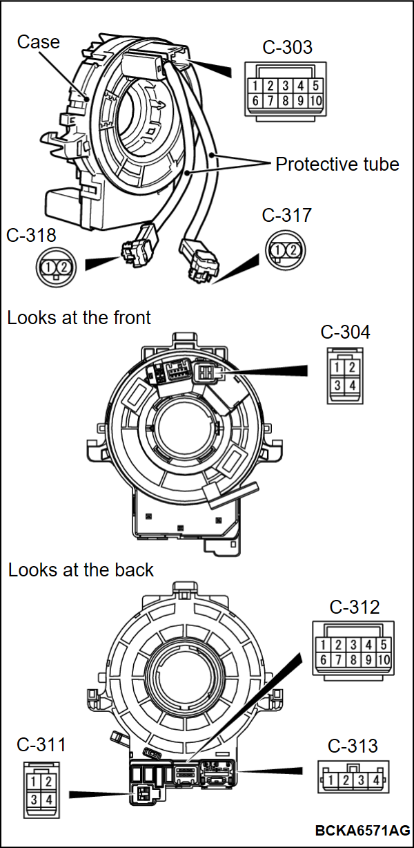
3. Check that the continuity exists between the following connector terminals.
<Driver's air bag module>
- C-313 connector terminal No. 1 and C-318 connector terminal No. 1
- C-313 connector terminal No. 2 and C-318 connector terminal No. 2
- C-313 connector terminal No. 3 and C-317 connector terminal No. 2
- C-313 connector terminal No. 4 and C-317 connector terminal No. 1
<Horn>
- C-303 connector terminal No. 1 and C-312 connector terminal No. 1
<Steering wheel remote control switch>
- C-303 connector terminal No. 2 and C-312 connector terminal No. 2
- C-303 connector terminal No. 3 and C-312 connector terminal No. 3
- C-303 connector terminal No. 5 and C-312 connector terminal No. 5
<Cruise control switch>
- C-303 connector terminal No. 5 and C-312 connector terminal No. 5
- C-303 connector terminal No. 6 and C-312 connector terminal No. 6
- C-303 connector terminal No. 7 and C-312 connector terminal No. 7
- C-303 connector terminal No. 8 and C-312 connector terminal No. 8
- C-303 connector terminal No. 9 and C-312 connector terminal No. 9
<Steering heater>
- C-304 connector terminal No. 1 and C-311 connector terminal No. 2
- C-304 connector terminal No. 2 and C-311 connector terminal No. 1
- C-304 connector terminal No. 3 and C-311 connector terminal No. 4
- C-304 connector terminal No. 4 and C-311 connector terminal No. 3
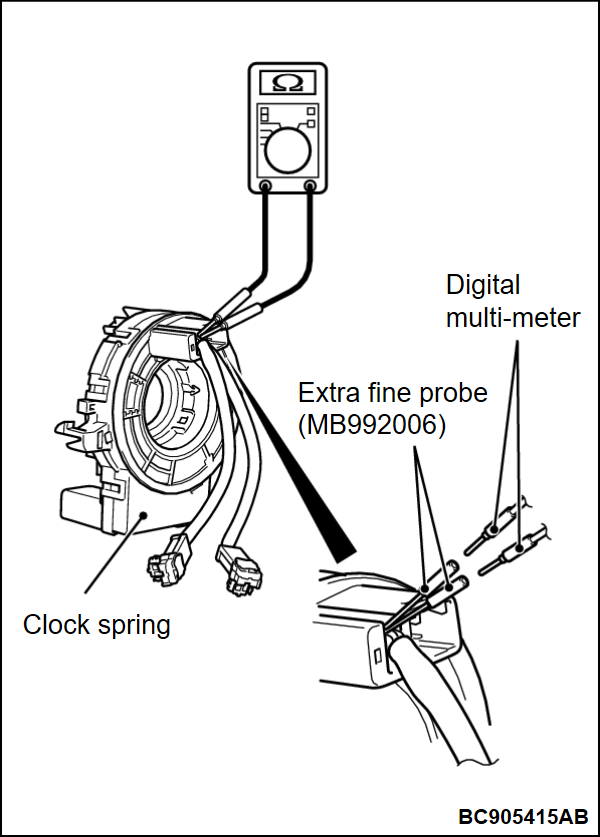
4. As shown in the Figure, connect the circuit tester to special tool extra fine probe (MB992006) and check to see that there is a charge between the terminals.
![[Previous]](../../../buttons/fprev.png)
![[Next]](../../../buttons/fnext.png)


