DIAGNOSTIC FUNCTION
Electric parking brake ECU has the following functions for easier system checks.
All the above items can be diagnosed using scan tool (M.U.T.-IIISE).
CHECK OF FREEZE FRAME DATA
The freeze frame data can be checked by using the scan tool (M.U.T.-IIISE).
When detecting fault and setting the DTC, the ECU connected to CAN bus line obtains the data before the determination of the DTC and the data when the DTC is determined, and then stores the ECU status of that time. By analyzing each data from scan tool (M.U.T.-IIISE), the troubleshooting can be performed more efficiently. The displayed items are as the table below.
Display item list
| Item No. | Item name | Data item | Unit |
| 1 | Odometer | Total driving distance after the DTC is generated | km/mile |
| 2 | Ignition cycle | Number of times the ignition switch is turned ON or LOCK (OFF) after the past failure transition | Number of counts is displayed. |
| 3 | Right actuator current | Right actuator current when the DTC is generated. | A |
| 4 | Left actuator current | Left actuator current when the DTC is generated. | A |
| 5 | Target current | Target current when the DTC is generated. | A |
| 6 | Control vehicle speed | Vehicle speed (wheel speed) when the DTC is generated | r/min |
| 7 | Power supply voltage | Voltage of power supply when the DTC is generated | V |
| 8 | Parking brake status | Electric parking brake control when the DTC is generated: Release/Lock/Lock -> Release/Release -> Lock/Unde- termined/EPB dynamic BRK/ASC dynamic BRK | - |
| 9 | EPB switch: LOCK 1 SW | Electric parking brake switch (Lock switch 1) condition when the DTC is generated: OFF/ON/Open/Short | - |
| 10 | EPB switch: LOCK 2 SW | Electric parking brake switch (Lock switch 2) condition when the DTC is generated: OFF/ON/Open/Short | - |
| 11 | EPB switch: RELEASE 1 SW | Electric parking brake switch (Release switch 1) condition when the DTC is generated: OFF/ON/Open/Short | - |
| 12 | EPB switch: RELEASE 2 SW | Electric parking brake switch (Release switch 2) condition when the DTC is generated: OFF/ON/Open/Short | - |
| 13 | Ignition switch (Hard wire) | IG1 signal (hard wire) condition when the DTC is generated: OFF/ON | - |
| 14 | Acceleration pedal | Accelerator pedal position sensor condition when the DTC is generated: OFF/ON | - |
| 15 | Shift information | Shift condition when the DTC is generated: P/R/N/D | - |
| 16 | Driver's seat belt | Driver's seat belt condition when the DTC is generated.: Not fastened/Fastened | - |
| 17 | Ignition switch (CAN) | IG1 signal (CAN signal) condition when the DTC is generated: OFF/ON | - |
| 18 | Run mode (PHEV) | Not used. | - |
| 19 | Master cylinder pressure | Master cylinder pressure of Master cylinder pressure sensor when the DTC is generated. | MPa/psi |
| 20 | Longitudinal G | Longitudinal G of G and when the DTC is generated. | m/s2 |
| 21 | Engine Torque (except PHEV) | Engine torque condition when the DTC is generated. | Nm |
| 22 | Motor Torque (PHEV) | Not used. | - |
FAIL-SAFE FUNCTIONS
When the electric parking brake ECU detects any malfunction in the system, the ECU will activate the brake warning light, the electric parking brake warning light and the electric parking brake switch indicator light to inform the driver that the electric parking brake is disabled.
In addition, the ECU displays a warning notice on the multi-information display in the combination meter.
Illumination condition of warning light, indicator light and multi information display in case of failure
| DTC | Inspection item | Brake warning light | Electric parking brake warning light | Multi information display | Electric parking brake switch indicator light |
| C1607 | ECU failure | OFF*4 | ON | PARKING BRAKE SERVICE REQUIRED | OFF*4 |
| C1707 | Implausible coding data | OFF*4 | ON | PARKING BRAKE SERVICE REQUIRED | OFF*4 |
| C1861 | Power supply low voltage | Flash (1 Hz) | OFF | - | Flash (1 Hz) |
| C2253 | EPB SW malfunction | Flash (1 Hz)*1 | ON | PARKING BRAKE SERVICE REQUIRED | Flash (1 Hz)*1 |
| C2254 | IG SW malfunction | OFF*4 | ON | PARKING BRAKE SERVICE REQUIRED | OFF*4 |
| C2300 | Left actuator malfunction | Flash (1 Hz) | ON | PARKING BRAKE SERVICE REQUIRED | Flash (1 Hz) |
| C2301 | Right Actuator malfunction | Flash (1 Hz) | ON | PARKING BRAKE SERVICE REQUIRED | Flash (1 Hz) |
| C2302 | Left Motor malfunction | OFF*4 | ON | PARKING BRAKE SERVICE REQUIRED | OFF*4 |
| C2303 | Right Motor malfunction | OFF*4 | ON | PARKING BRAKE SERVICE REQUIRED | OFF*4 |
| C2304 | Left +B voltage malfunction | OFF*4 | ON | PARKING BRAKE SERVICE REQUIRED | OFF*4 |
| C2305 | Right +B voltage malfunction | OFF*4 | ON | PARKING BRAKE SERVICE REQUIRED | OFF*4 |
| U0100 | Engine CAN timeout | OFF*4 | ON | PARKING BRAKE SERVICE REQUIRED | OFF*4 |
| U0101 | T/M CAN timeout | OFF*4 | ON | PARKING BRAKE SERVICE REQUIRED | OFF*4 |
| U0121 | ABS/ASC CAN timeout | OFF*4 | ON | PARKING BRAKE SERVICE REQUIRED | OFF*4 |
| U0141 | ETACS CAN timeout | OFF*4 | ON | PARKING BRAKE SERVICE REQUIRED | OFF*4 |
| U0401 | Engine (CAN message) | OFF*4 | ON | PARKING BRAKE SERVICE REQUIRED | OFF*4 |
| U0402 | T/M (CAN message) | OFF*4 | ON | PARKING BRAKE SERVICE REQUIRED | OFF*4 |
| U0415 | ABS/ASC (CAN message) | OFF*4 | ON | PARKING BRAKE SERVICE REQUIRED | OFF*4 |
| U1073 | Bus-off | OFF*4 | ON | PARKING BRAKE SERVICE REQUIRED | OFF*4 |
| U1195 | Coding not completed | OFF*4 | ON | PARKING BRAKE SERVICE REQUIRED | OFF*4 |
| - | The power supply voltage is abnormal*2. | Flash (1 Hz) | OFF | - | Flash (1 Hz) |
| - | The system detects a continuous operation of the electric parking brake (to protect the electric motor from overheat)*3. | Flash (1 Hz) | OFF | PARKING BRAKE TEMPORARILY NOT AVAILABLE | Flash (1 Hz) |
| - | The system detects that the electric parking brake is engaged poorly (the vehicle moves) continuously. | Flash (1 Hz) | OFF | - | Flash (1 Hz) |
| note |
|
Under apply, release and emergency brake*1 in case of failure
| DTC | Inspection item | Apply | Release*2 | Emergency brake (ASC)*3 | Emergency brake (EPB)*4 |
| C1607 | ECU failure | Enabled*5 | Enabled*5 | Enabled*5 | Enabled*5 |
| C1707 | Implausible coding data | Enabled | Enabled | Enabled | Enabled |
| C1861 | Power supply low voltage | Prohibited | Enabled | Enabled | Prohibited |
| C2253 | EPB SW malfunction | Prohibited | Prohibited*6/Enabled*7 | Prohibited | Prohibited |
| C2254 | IG SW malfunction | Enabled | Enabled | Enabled | Enabled |
| C2300 | Left actuator malfunction | Enabled*8 | Enabled*8 | Enabled*8 | Enabled*8 |
| C2301 | Right Actuator malfunction | Enabled*8 | Enabled*8 | Enabled*8 | Enabled*8 |
| C2302 | Left Motor malfunction | Enabled*8 | Enabled*8 | Enabled*8 | Enabled*8 |
| C2303 | Right Motor malfunction | Enabled*8 | Enabled*8 | Enabled*8 | Enabled*8 |
| C2304 | Left +B voltage malfunction | Enabled*8 | Enabled*8 | Enabled*8 | Enabled*8 |
| C2305 | Right +B voltage malfunction | Enabled*8 | Enabled*8 | Enabled*8 | Enabled*8 |
| U0100 | Engine CAN timeout | Enabled | Enabled | Enabled | Enabled |
| U0101 | T/M CAN timeout | Enabled | Enabled | Enabled | Enabled |
| U0121 | ABS/ASC CAN timeout | Prohibited | Enabled | Prohibited | Enabled*9 |
| U0141 | ETACS CAN timeout | Enabled | Enabled | Enabled | Enabled |
| U0401 | Engine (CAN message) | Enabled | Enabled | Enabled | Enabled |
| U0402 | T/M (CAN message) | Enabled | Enabled | Enabled | Enabled |
| U0415 | ABS/ASC (CAN message) | Enabled*9 | Enabled | Enabled*9 | Enabled*9 |
| U1073 | Bus-off | Prohibited | Enabled*12 | Prohibited | Enabled*9 |
| U1195 | Coding not completed | Enabled | Enabled | Enabled | Enabled |
| - | The power supply voltage is abnormal*10. | Prohibited | Prohibited | Prohibited | Prohibited |
| - | The system detects a continuous operation of the electric parking brake (to protect the electric motor from overheat) *11 | Prohibited | Enabled | Enabled | Enabled*4 |
| - | The system detects that the electric parking brake is engaged poorly (the vehicle moves) continuously. | Enabled | Enabled | Enabled | Prohibited |
| note |
|
HOW TO CONNECT THE SCAN TOOL (M.U.T.-IIISE)
| caution | To prevent damage to scan tool (M.U.T.-IIISE), always turn the ignition switch to the "LOCK" (OFF) position before connecting or disconnecting scan tool (M.U.T.-IIISE). |
1. Ensure that the ignition switch is at the "LOCK" (OFF) position.
2. Start up the personal computer.
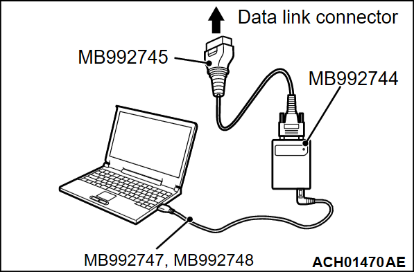
3. Connect special tool MB992747/M992748 to special tool MB992744 and the personal computer.
4. Connect special tool MB992745 to special tool MB992744.
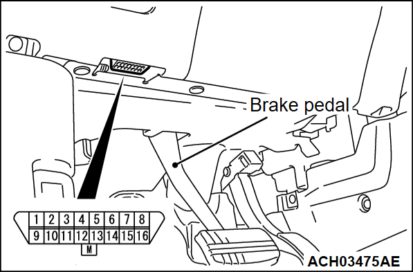
5. Connect special tool MB992745 to the data link connector.
| note | When the special tool MB992745 is connected to the data link connector, the special tool MB992744 indicator light will be illuminated in a green color. |
6. Start the M.U.T.-IIISE system on the personal computer.
| note | Disconnecting scan tool (M.U.T.-IIISE) is the reverse of the connecting sequence, first making sure that the ignition switch is at the "LOCK" (OFF) position. |
HOW TO READ AND ERASE DIAGNOSTIC TROUBLE CODES
| note | If the Battery voltage is low, diagnostic trouble codes will not be set. Check the battery if scan tool (M.U.T.-IIISE) does not display. |
1. Connect scan tool (M.U.T.-IIISE) to the data link connector.
2. Turn the ignition switch to the "ON" position.
3. Select "STV".
4. Select "EPB".
5. Select "Diagnostic Trouble Code" to read the DTC.
6. If a DTC is set, it is shown.
7. Choose "Erase DTCs" to erase the DTC.
HOW TO DIAGNOSE THE CAN BUS LINES
1. Connect scan tool (M.U.T.-IIISE) to the data link connector.
2. Turn the ignition switch to the "ON" position.
3. Select "CAN bus diagnosis" from the system select screen.
4. When the optional equipment screen is displayed, choose the one which the vehicle is fitted with, and then select the "OK" button.
![[Previous]](../../../buttons/fprev.png)
![[Next]](../../../buttons/fnext.png)


