[Previous][Next]
REMOVAL AND INSTALLATION
 
 
caution
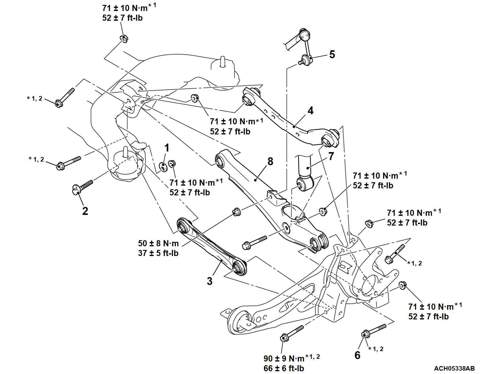
  • The parts indicated by *1 should be temporarily tightened, and then fully tightened with the vehicle standing on the ground virtually and the curb weight condition.
  • *2 Indicates the bolts with stabilizer for coefficient of friction. When you tighten it, note the following:
    • Check the bolts for any damage.
    • Clean the seating and thread of the bolts.
    • Observe the specified torque.
Pre-removal Operation
  • Rear Wheel Speed Sensor Removal (Refer to GROUP 35C - Wheel Speed Sensor ).
Post-installation Operation
  • Using Your Fingers, Press the Ball Joint Dust Cover to Check for a Crack or Damage.
  • Rear Wheel Speed Sensor Installation (Refer to GROUP 35C - Wheel Speed Sensor ).
  • Wheel Alignment Check and Adjustment (Refer to ).
  • Check the Beam Direction of the Headlight (Low Beam) (Refer to GROUP 54A - Headlight Aiming ).
Control link and upper arm removal
1.Plate
<<A>>>>D<<2.Toe adjusting bolt
>>C<<3.Control link
>>B<<4.Upper arm
Lower arm removal steps
<<B>>>>A<<5.Stabilizer link connection
<<C>>6.Lower arm and trailing arm connection
<<C>>7.Shock absorber and lower arm connection
8.Lower arm
 
 
REMOVAL SERVICE POINTS
 
 
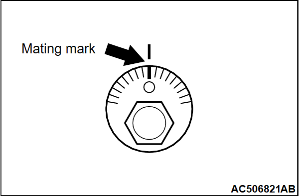
<<A>> TOE ADJUSTING BOLT REMOVAL
Align the marks made on the toe adjustment bolt removal.


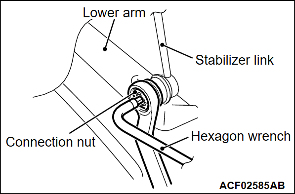
<<B>> STABILIZER LINK DISCONNECTION
Use a hexagon wrench to counterhold the stabilizer link as shown. Then use a wrench to remove the nut securing the stabilizer link to the lower arm.


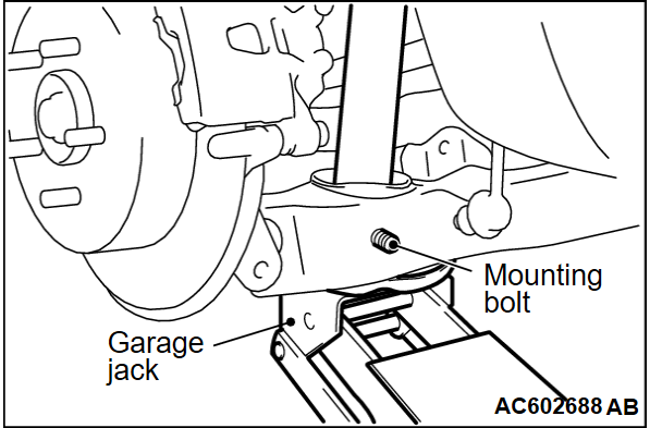
<<C>> LOWER ARM AND TRAILING ARM/SHOCK ABSORBER AND LOWER ARM DISCONNECTION
While jacking-up the lower arm with garage jack, remove the mounting bolts.


INSTALLATION SERVICE POINTS
 
 
>>A<< STABILIZER LINK CONNECTION
Use a hexagon wrench to counterhold the stabilizer link as shown. Then use a wrench to install the nut securing the stabilizer link to the lower arm.


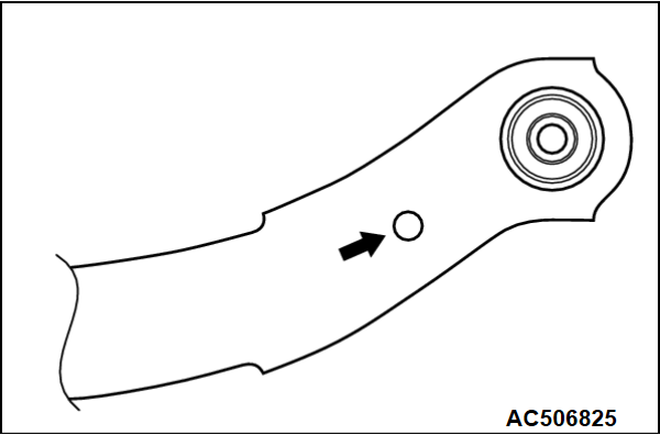
>>B<< UPPER ARM INSTALLATION
Install the upper arm so that the hole faces the body side.


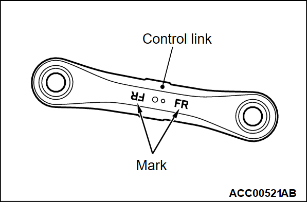
>>C<< CONTROL LINK INSTALLATION
Make sure that "FR" mark stamped on the control link points to the vehicle front.


>>D<< TOE ADJUSTING BOLT INSTALLATION
Align the marks made on the toe adjustment bolt removal.