DTC P0132: Linear Air-Fuel Ratio Sensor Circuit High Voltage
CIRCUIT OPERATION
The linear air-fuel ratio sensor and the ECM are connected by the following three lines to detect the air-fuel ratio.
- The line between the linear air-fuel ratio sensor and the ECM terminal LPFL detects the air-fuel ratio.
- The auxiliary line between the linear air-fuel ratio sensor and the ECM terminal LSFL detects the air-fuel ratio.
- The line between the linear air-fuel ratio sensor and the ECM terminal LEFL is connected to ground.
TECHNICAL DESCRIPTION
- The ECM effects air/fuel ratio feedback control in accordance with the signals from the linear air-fuel ratio sensor.
- If the linear air-fuel ratio sensor has deteriorated, corrections will be made by the heated oxygen sensor (rear).
DESCRIPTIONS OF MONITOR METHODS
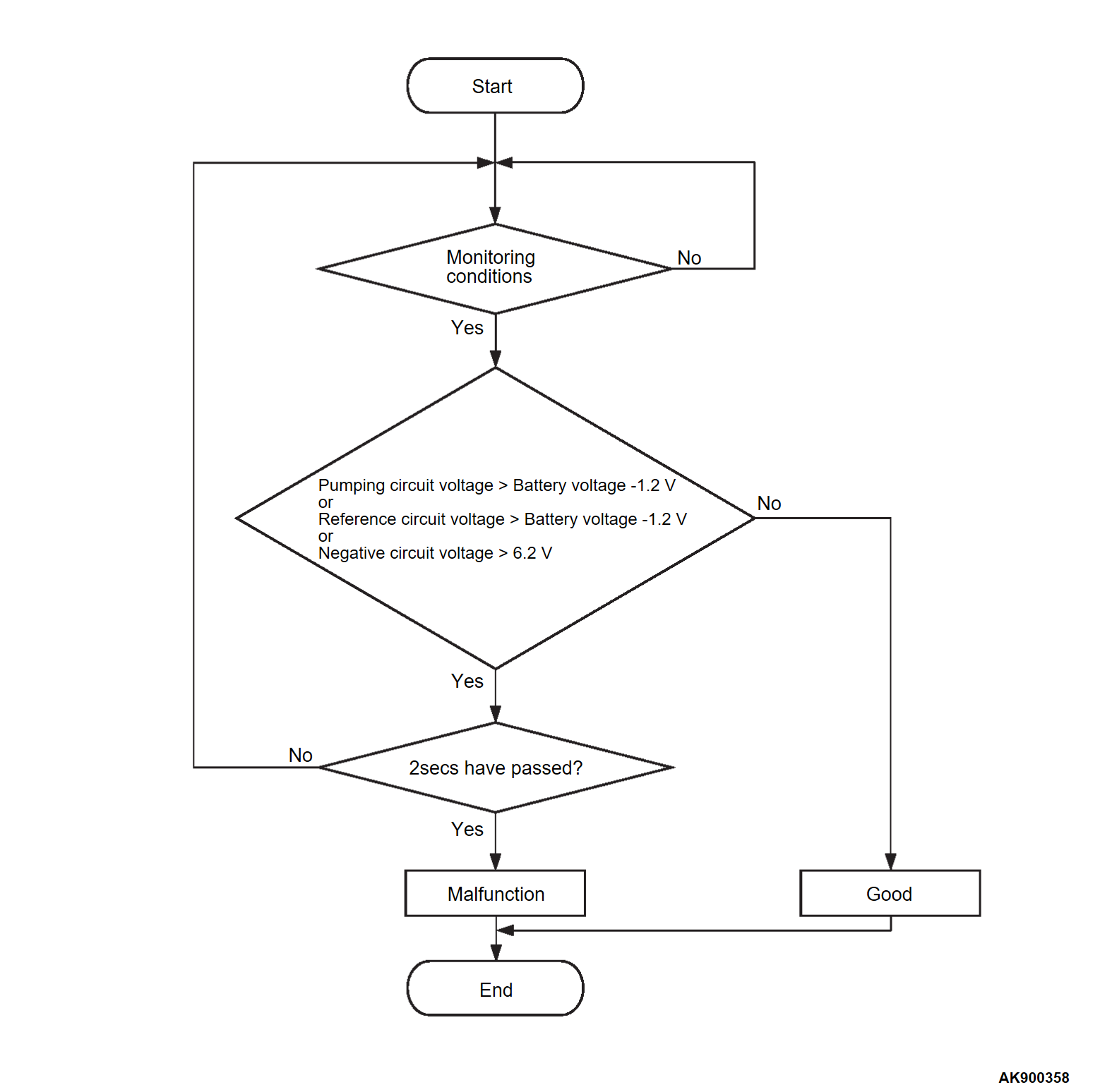
- If one of the three line voltages is excessively high or if all the three line voltages are excessively high, the DTC is set as a malfunction.
MONITOR EXECUTION
- Continuous
MONITOR EXECUTION CONDITIONS (Other monitor and Sensor)
Other Monitor (There is no temporary DTC set in memory for the item monitored below)
- Linear air-fuel ratio sensor heater monitor
- Misfire monitor
- Fuel system monitor
Sensor (The sensor below is determined to be normal)
- Mass airflow sensor
- Engine coolant temperature sensor
- Intake air temperature sensor 1
- Barometric pressure sensor
- Throttle position sensor
- Accelerator pedal position sensor
Check Conditions
- Battery positive voltage is between 10 and 16.5 volts.
- More than 40 seconds have passed since the engine starting sequence was completed.
Judgment Criterion
- The pumping circuit voltage is higher than the battery positive voltage from which you subtract 1.2 volt for 2 seconds.
or
- The reference circuit voltage is higher than battery positive voltage from which you subtract 1.2 volt for 2 seconds.
or
- The negative circuit voltage is be higher than 6.2 volts for 2 seconds.
FAIL-SAFE AND BACKUP FUNCTION
- Does not control air-fuel ratio closed loop.
TROUBLESHOOTING HINTS (The most likely causes for this code to be set are: )
- Linear air-fuel ratio sensor failed.
- Shorted linear air-fuel ratio sensor circuit, or connector damage.
- ECM failed.
DIAGNOSIS
STEP 1. Check of short circuit to power supply in LSFL line between linear air-fuel ratio sensor connector and ECM connector.
Is the harness wire in good condition?
STEP 2. Check of short circuit to power supply in LPFL line between linear air-fuel ratio sensor connector and ECM connector.
Is the harness wire in good condition?
STEP 3. Check of short circuit to power supply in LEFL line between linear air-fuel ratio sensor connector and ECM connector.
Is the harness wire in good condition?
STEP 4. Replace the linear air-fuel ratio sensor.
(1) Replace the linear air-fuel ratio sensor.
(2) Carry out a test drive with the drive cycle pattern. Refer to Diagnostic Function - OBD-II Drive Cycle - Pattern 1  .
.
 .
.(3) Check the diagnostic trouble code (DTC).
Is DTC P0132 set?
 The inspection is complete.
![[Previous]](../../../buttons/fprev.png)
![[Next]](../../../buttons/fnext.png)

