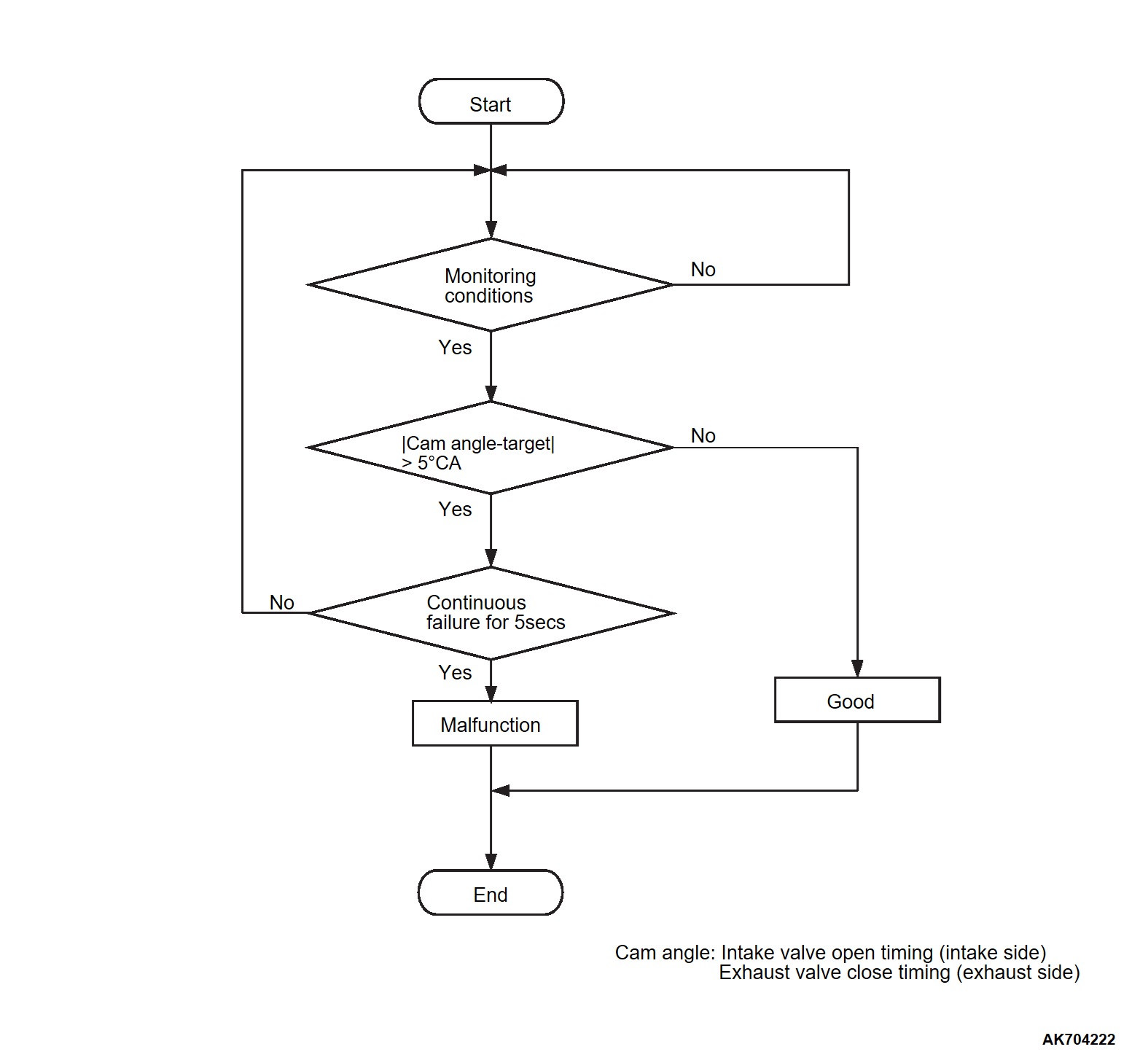
DTC P0011: Intake Variable Valve Timing System Target Error
TECHNICAL DESCRIPTION
- The ECM controls the spool valve position of the intake engine oil control valve corresponding to the driving condition of the engine and continuously changes the phase of the intake camshaft.
- The phase angle of the intake camshaft is computed from the signal patterns of the crank angle sensor and intake camshaft position sensor.
DESCRIPTIONS OF MONITOR METHODS
- The difference between the actual intake valve opening timing and the intake valve target opening timing is over the specified value.
MONITOR EXECUTION
- Continuous
MONITOR EXECUTION CONDITIONS (Other monitor and Sensor)
Other Monitor (There is no temporary DTC set in memory for the item monitored below)
- Not applicable
Sensor (The sensor below is determined to be normal)
- Camshaft position sensor
- Crankshaft position sensor
- Engine coolant temperature sensor
- Throttle position sensor
- Engine oil control valve
DTC SET CONDITIONS
Check Conditions
- More than 20 seconds have passed since the engine starting sequence was completed.
- Engine speed is more than 1,188 r/min.
- Engine coolant temperature is higher than 76°C (169°F).
Judgment Criterion
- The difference between the actual intake valve opening timing and the intake valve target opening timing is more than 5 degrees for 5 seconds.
FAIL-SAFE AND BACKUP FUNCTION
- None.
TROUBLESHOOTING HINTS (The most likely causes for this code to be set are: )
- Intake engine oil control valve failed.
- Harness damage in intake engine oil control valve circuit or loose connector contact.
- Failed timing sprocket operation.
- Clogged oil passage.
- Intake camshaft failed.
- ECM failed.
DIAGNOSIS
STEP 1. Using scan tool (M.U.T.-IIISE), check data list item 36: Intake MIVEC phase angle.
| caution | To prevent damage to scan tool (M.U.T.-IIISE), always turn the ignition switch to the "LOCK" (OFF) position before connecting or disconnecting scan tool (M.U.T.-IIISE). |
(1) Connect scan tool (M.U.T.-IIISE) to the data link connector.
(2) Start the engine.
(3) Set scan tool (M.U.T.-IIISE) to the data reading mode for item 36, Intake MIVEC phase angle.
- When the idle operation with no load, -5.7 to 11.8 °CA (ATDC).
- When the high load operation, Decreases (advances).
(4) Turn the ignition switch to the "LOCK" (OFF) position.
Are they operating properly?
STEP 2. Check the intake engine oil control valve.
STEP 3. Check of harness damage in OCVI line between intake engine oil control valve connector and ECM connector.
Is the harness wire in good condition?
STEP 4. Check of harness damage in power supply line between MFI relay connector and intake engine oil control valve connector.
Is the harness wire in good condition?
STEP 5. Check intake camshaft sensing ring.
STEP 6. Check intake variable valve timing sprocket operation mechanism for being stuck.
STEP 7. Check oil passage of intake variable valve timing control system for being clogged.
![[Previous]](../../../buttons/fprev.png)
![[Next]](../../../buttons/fnext.png)


