DTC P0191: Fuel Rail Pressure Circuit Range/Performance Problem
CIRCUIT OPERATION
TECHNICAL DESCRIPTION
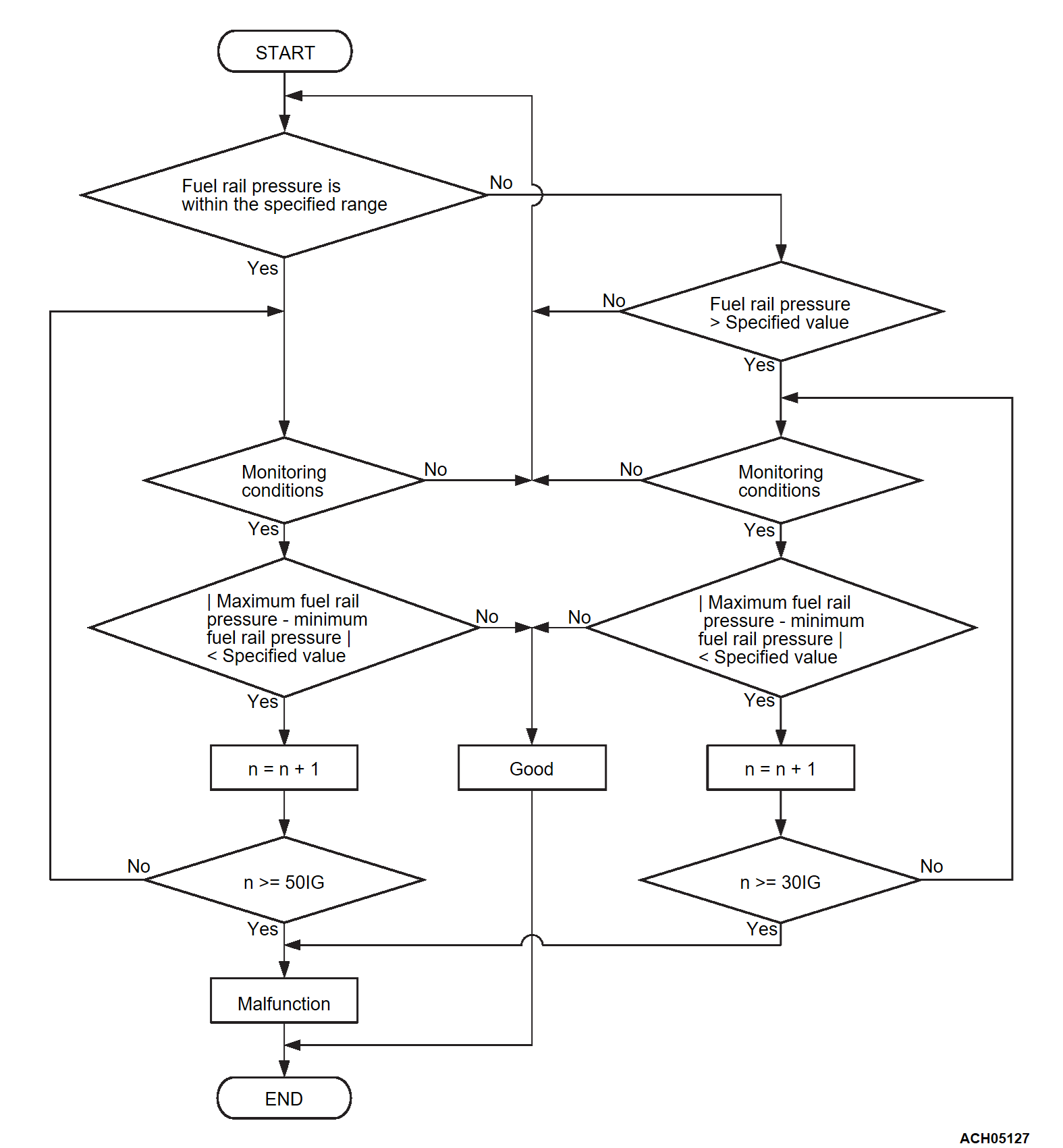
ECM checks the fuel rail pressure sensor output signal characteristics for abnormal conditions.
MONITOR EXECUTION
- Continuous
MONITOR EXECUTION CONDITIONS (Other monitor and Sensor)
Other Monitor (There is no temporary DTC set in memory for the item monitored below)
- Not applicable
Sensor (The sensor below is determined to be normal)
- Not applicable
DTC SET CONDITIONS
Check Conditions
- Engine starting sequence was completed.
- Battery positive voltage is higher than 10 volts.
- Fuel rail pressure at monitor start is within the specified range.
Judgment Criterion
- During the drive cycle, the ECM performs monitoring with the total ignition of 50.
- The absolute value of the difference between the maximum fuel rail pressure and the minimum fuel rail pressure has continued to be less than the specified value.
Check Conditions
- Engine starting sequence was completed.
- Battery positive voltage is higher than 10 volts.
- Fuel rail pressure at monitor start is higher than the specified value.
- Fuel rail pressure at monitor start is higher than target fuel rail pressure.
- Fuel injection mode is not MFI-mode.
Judgment Criterion
- During the drive cycle, the ECM performs monitoring with the total ignition of 30.
- The absolute value of the difference between the maximum fuel rail pressure and the minimum fuel rail pressure has continued to be less than the specified value.
FAIL-SAFE AND BACKUP FUNCTION
- While prohibiting the operation of the injector (high pressure), carry out the control by the injector operation only.
- Torque is restricted.
TROUBLESHOOTING HINTS (The most likely causes for this code to be set are: )
- Fuel rail pressure sensor failed.
- Injector (high pressure) failed.
- Fuel pump (high pressure) failed.
- Open or Shorted fuel rail pressure sensor circuit, harness damage or connector damage.
- High-pressure fuel line clogged.
- Fuel rail (high pressure) failed.
- ECM failed.
DIAGNOSIS
| note | This DTC can be output for an air penetration in the fuel line due to lack of fuel. Therefore, bleed air from the fuel line after the fuel supply, and delete the DTC through scan tool (M.U.T.-IIISE). |
Required Special Tool:
- MB991709: Test Harness
STEP 1. Using scan tool (M.U.T.-IIISE), read the diagnostic trouble code (DTC).
| caution | To prevent damage to scan tool (M.U.T.-IIISE), always turn the ignition switch to the "LOCK" (OFF) position before connecting or disconnecting scan tool (M.U.T.-IIISE). |
(2) Turn the ignition switch to the "ON" position.
(3) Set scan tool (M.U.T.-IIISE), read the DFI and MFI-DTC.
(4) Turn the ignition switch to the "LOCK" (OFF) position.
Is the diagnostic trouble code other than P0191 set?
STEP 2. Check of open circuit, short circuit and harness damage in HFP5 line between fuel rail pressure sensor connector and ECM connector.
Is the harness wire in good condition?
STEP 3. Check of short circuit and harness damage in HFPS line between fuel rail pressure sensor connector and ECM connector.
Is the harness wire in good condition?
STEP 4. Check of short circuit and harness damage in HFPG line between fuel rail pressure sensor connector and ECM connector.
Is the harness wire in good condition?
STEP 5. Measure the sensor output voltage at fuel rail pressure sensor connector.
(1) Using test harness special tool MB991709 to connect connector, and measure at pick-up harness.
(2) Measure the voltage between terminal HFPS line and ground.
- The output voltage of the fuel pressure sensor changes before starting and after starting.
Is the measured voltage normal?
STEP 6. Check of harness damage in HFP+ line between fuel pump (high pressure) connector and ECM connector.
Is the harness wire in good condition?
STEP 7. Check of harness damage in HFP- line between fuel pump (high pressure) connector and ECM connector.
Is the harness wire in good condition?
STEP 8. Check the trouble symptoms.
(1) Carry out a test drive with the drive cycle pattern. Refer to Diagnostic Function - OBD-II Drive Cycle - Pattern 1  .
.
 .
.(2) Check the diagnostic trouble code (DTC).
Is DTC P0191 set?
STEP 9. Check the trouble symptoms.
(1) Carry out a test drive with the drive cycle pattern. Refer to Diagnostic Function - OBD-II Drive Cycle - Pattern 1  .
.
 .
.(2) Check the diagnostic trouble code (DTC).
Is DTC P0191 set?
 The inspection is complete.
![[Previous]](../../../buttons/fprev.png)
![[Next]](../../../buttons/fnext.png)

