![[Previous]](../../../BUTTONS/fprev.png)
![[Next]](../../../BUTTONS/fnext.png)
| DTC 43: SRS Warning Light Drive Circuit System Fault 1 (Light does not Illuminate). | |||||||||||||||||||||||||||||||||||||||||||||||||||||||||||||||||||||||||||||||
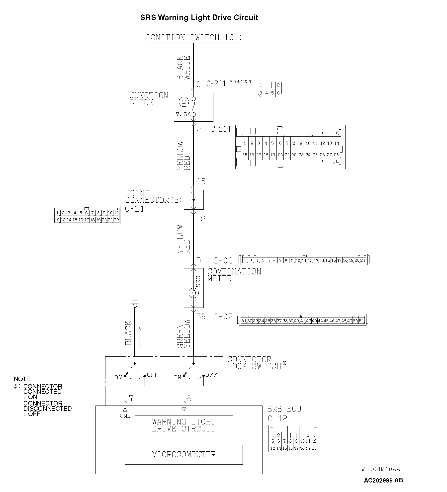
DIAGNOSIS Required Special Tools: MB991958: Scan Tool (MUT-III Sub Assembly) MB991824: Vehicle Communication Interface (V.C.I.) MB991827: MUT-III USB Cable MB991911: MUT-III Main Harness B (Vehicles without CAN communication system) |
|||||||||||||||||||||||||||||||||||||||||||||||||||||||||||||||||||||||||||||||
STEP 1. Check the SRS warning light. |
|||||||||||||||||||||||||||||||||||||||||||||||||||||||||||||||||||||||||||||||
(1) Disconnected the SRS-ECU connector C-12. (2) Connect the negative battery terminal. (3) Turn the ignition switch to the "ON" position. Q: Does the warning light illuminate? YES: Erase the diagnostic trouble code memory, and check the diagnostic trouble code. If DTC 43 sets, replace the SRS-ECU (Refer to NO: Go to Step 2 |
|||||||||||||||||||||||||||||||||||||||||||||||||||||||||||||||||||||||||||||||
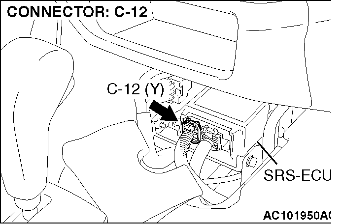
STEP 2. Check the ground line at the SRS-ECU connector C-12. (1) Disconnect the negative battery terminal. |
|||||||||||||||||||||||||||||||||||||||||||||||||||||||||||||||||||||||||||||||
(2) Disconnect SRS-ECU connector C-12. |
|||||||||||||||||||||||||||||||||||||||||||||||||||||||||||||||||||||||||||||||
Do not insert a test probe into the terminal from its front side directly as the connector contact pressure may be weakened. (3) Check for continuity between C-12 harness connector terminal 7 and ground. It should be less than 2 ohms. Q: Does continuity exist? YES: Go to Step 3 NO: Go to Step 5 |
|||||||||||||||||||||||||||||||||||||||||||||||||||||||||||||||||||||||||||||||
STEP 3. Check the SRS warning light bulb. |
|||||||||||||||||||||||||||||||||||||||||||||||||||||||||||||||||||||||||||||||
| Q: Has the SRS warning light bulb blown? YES: Replace the SRS warning light bulb. Then go to Step 6 NO: Go to Step 4 |
|||||||||||||||||||||||||||||||||||||||||||||||||||||||||||||||||||||||||||||||
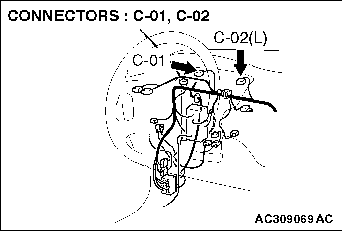
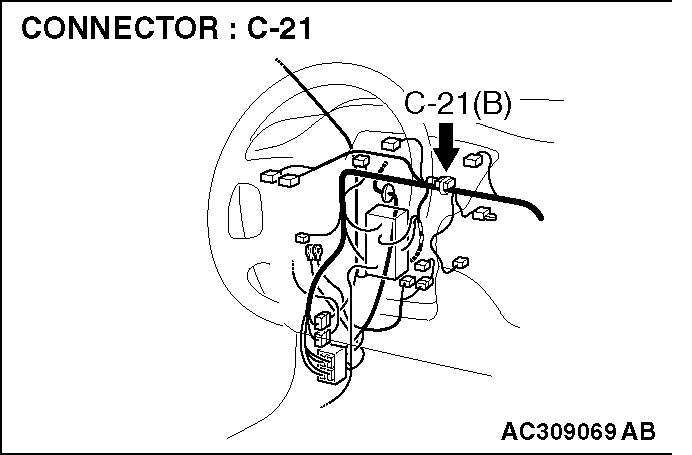
STEP 4. Check the harness for open circuit between ignition switch connector C-208 (terminal No.2) and combination meter connector C-01 (terminal No.9), and between combination meter connector C-02 (terminal No.36) and SRS-ECU connector C-12 (terminal No.8). |
|||||||||||||||||||||||||||||||||||||||||||||||||||||||||||||||||||||||||||||||
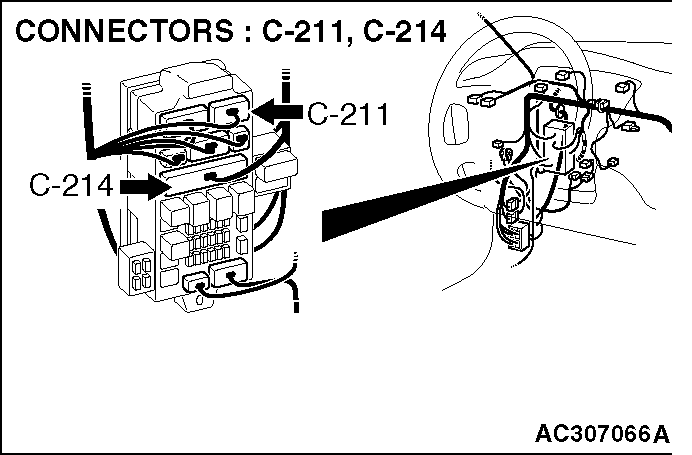
NOTE: |
|||||||||||||||||||||||||||||||||||||||||||||||||||||||||||||||||||||||||||||||
| After inspecting intermediate connectors C-21, C-214, C-211 inspect the wiring harness. If intermediate connectors C-21, C-214, C-211 are damaged, repair or replace them. Refer to GROUP 00E, Harness Connector Inspection Q: Are the harness wires between SRS-ECU connector C-12 and the ignition switch connector C-208 in good condition? YES: Replace the combination meter (Refer to GROUP 54A, Combination Meters Assembly NO: Repair the harness wires between SRS-ECU connector C-12 and the ignition switch connector C-208. Then go to Step 6 |
|||||||||||||||||||||||||||||||||||||||||||||||||||||||||||||||||||||||||||||||
STEP 5. Check the harness for open circuit between SRS-ECU connector C-12 (terminal No.7) and ground. |
|||||||||||||||||||||||||||||||||||||||||||||||||||||||||||||||||||||||||||||||
| Q: Is the harness wire between SRS-ECU connector C-12 (terminal No.7) and ground in good condition? YES: Go to Step 6 NO: Repair the harness wires between SRS-ECU connector C-12 and ground. Then go to Step 6 |
|||||||||||||||||||||||||||||||||||||||||||||||||||||||||||||||||||||||||||||||
STEP 6. Recheck for diagnostic trouble code. Q: Is DTC 43 set? YES: Return to Step 1 NO: The procedure is complete (If no malfunctions are found in all steps, an intermittent malfunction is suspected. Refer to GROUP 00, How to Use Troubleshooting/Inspection Service Points - How to Cope with Intermittent Malfunction |
|||||||||||||||||||||||||||||||||||||||||||||||||||||||||||||||||||||||||||||||