CIRCUIT OPERATION
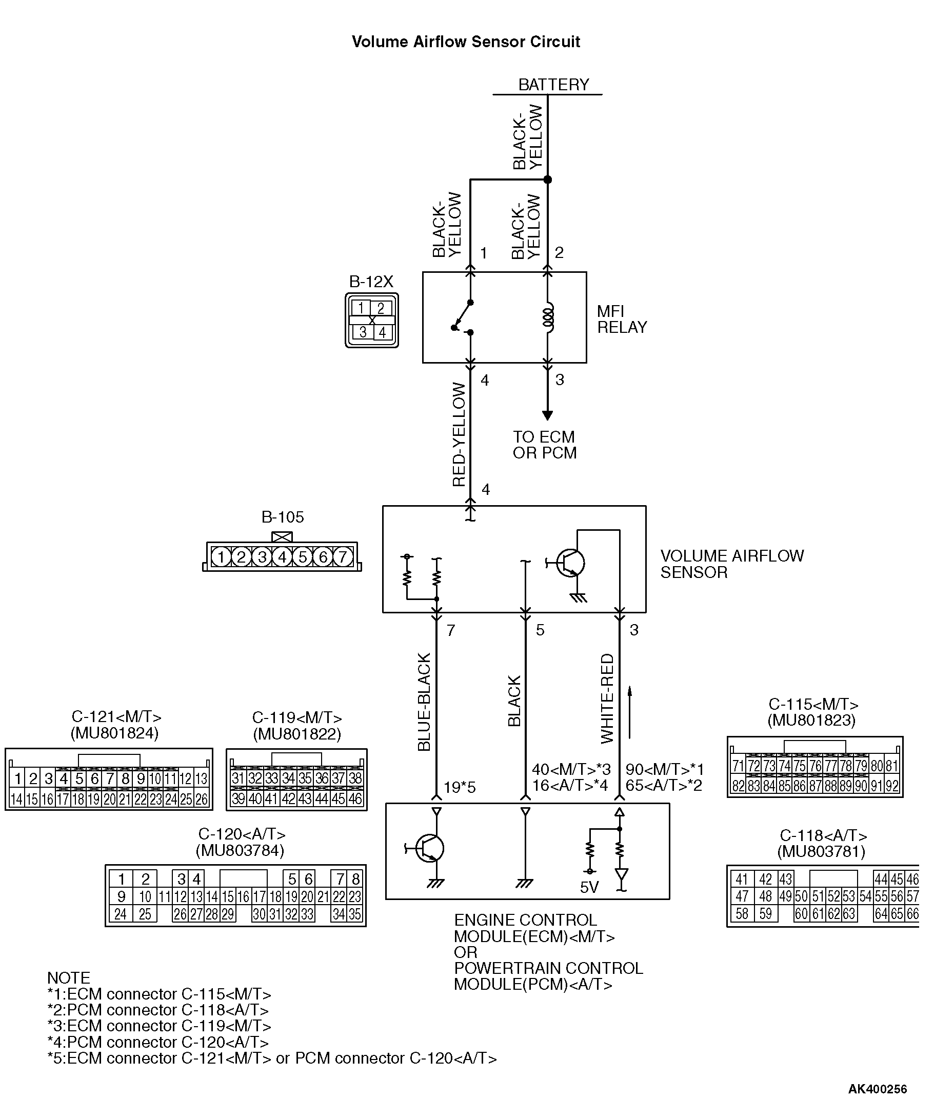
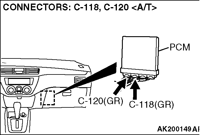
• The volume airflow sensor power is supplied from the MFI relay (terminal No. 4), and the ground is provided on the ECM (terminal No. 40) <M/T> or PCM (terminal No. 16) <A/T>.
• 5-volt power is applied to the volume airflow sensor output terminal (terminal No. 3) from the ECM (terminal No. 90) <M/T> or PCM (terminal No. 65) <A/T>. The volume airflow sensor generates a pulse signal when the output terminal and ground are opened/closed (opened/short). TECHNICAL DESCRIPTION
• While the engine is running, the volume airflow sensor outputs a pulse signal which corresponds to the volume of air flow.
• The ECM <M/T> or PCM <A/T> checks whether the frequency of this signal output by the volume airflow sensor while the engine is running is at or above the set value. DESCRIPTIONS OF MONITOR METHODS
• An open or short circuit is detected while monitoring the output frequency of the volume airflow sensor. MONITOR EXECUTION
Continuous MONITOR EXECUTION CONDITIONS (Other monitor and Sensor)
Other Monitor (There is no temporary DTC stored in memory for the item monitored below)
• Not applicable
Sensor (The sensor below is determined to be normal)
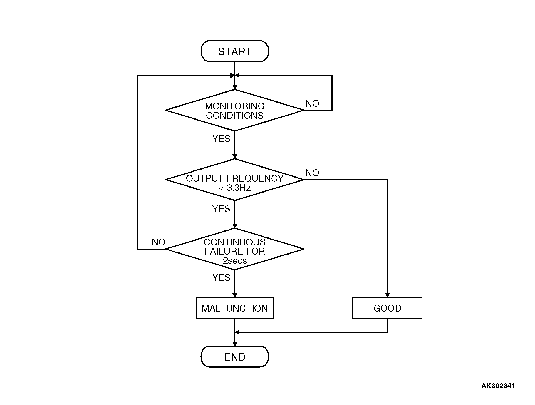
• Throttle position sensor DTC SET CONDITIONS Logic Flow Chart
Check Condition
Engine speed is higher than 500 r/min.
Judgement Criterion
• Volume airflow sensor output frequency has continued to be 3.3 Hz or lower for 2 seconds. OBD-II DRIVE CYCLE PATTERN
Refer to Diagnostic Function - OBD-II Drive Cycle - Pattern 19 . TROUBLESHOOTING HINTS (The most likely causes for this code to be set are: )
• Volume airflow sensor failed.
• Open or shorted volume airflow sensor circuit, or harness damage or connector damage.
• ECM failed. <M/T>
• PCM failed. <A/T>
• Air leak between volume airflow sensor and throttle body.
![[Previous]](../../../BUTTONS/fprev.png)
![[Next]](../../../BUTTONS/fnext.png)