[Previous][Next]
REMOVAL AND INSTALLATION
 
 
caution
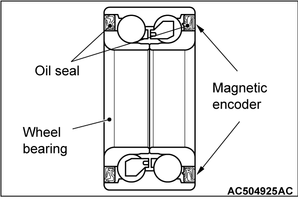
  • The magnetic encoder collects metallic particles easily, because it is magnetized. Make sure that the magnetic encoder should not collect metallic particles. Check that there is not any trouble prior to reassembling it.
  • When removing and installing the driveshaft assembly, make sure that the magnetic encoder (integrated with the inner oil seal) does not contact with surrounding parts to avoid damage.
  • When removing and installing the front wheel speed sensor, make sure that the pole piece at the end does not contact with surrounding parts to avoid damage.
Pre-removal operation
  • Engine room under cover front removal (Refer to GROUP 51, Under Cover Removal and Installation ).
  • Transmission oil draining (Refer to GROUP 22A, On-vehicle Service - Transmission Oil Change ). <M/T>
  • Transmission fluid draining (Refer to GROUP 23A, On-vehicle Service - Transmission Fluid Change ). <CVT>
  • Lower arm assembly and Stabilizer bar Connection Removal (Refer to GROUP 33, Stabilizer bar Removal and Installation ).
Post-installation operation
  • Using your fingers, press the Ball Joint Dust Cover to check for a crack or damage.
  • Lower arm assembly and Stabilizer bar Connection Installation (Refer to GROUP 33, Stabilizer bar Removal and Installation ).
  • Transmission oil refilling (Refer to GROUP 22A, On-vehicle Service - Transmission Oil Change ). <M/T>
  • Transmission fluid refilling (Refer to GROUP 23A, On-vehicle Service - Transmission Fluid Change ). <CVT>
  • Engine room under cover front installation (Refer to GROUP 51, Under Cover Removal and Installation ).
  • Check the beam direction of the headlight (Low beam) (Refer to GROUP 54A, Headlight Aiming ).
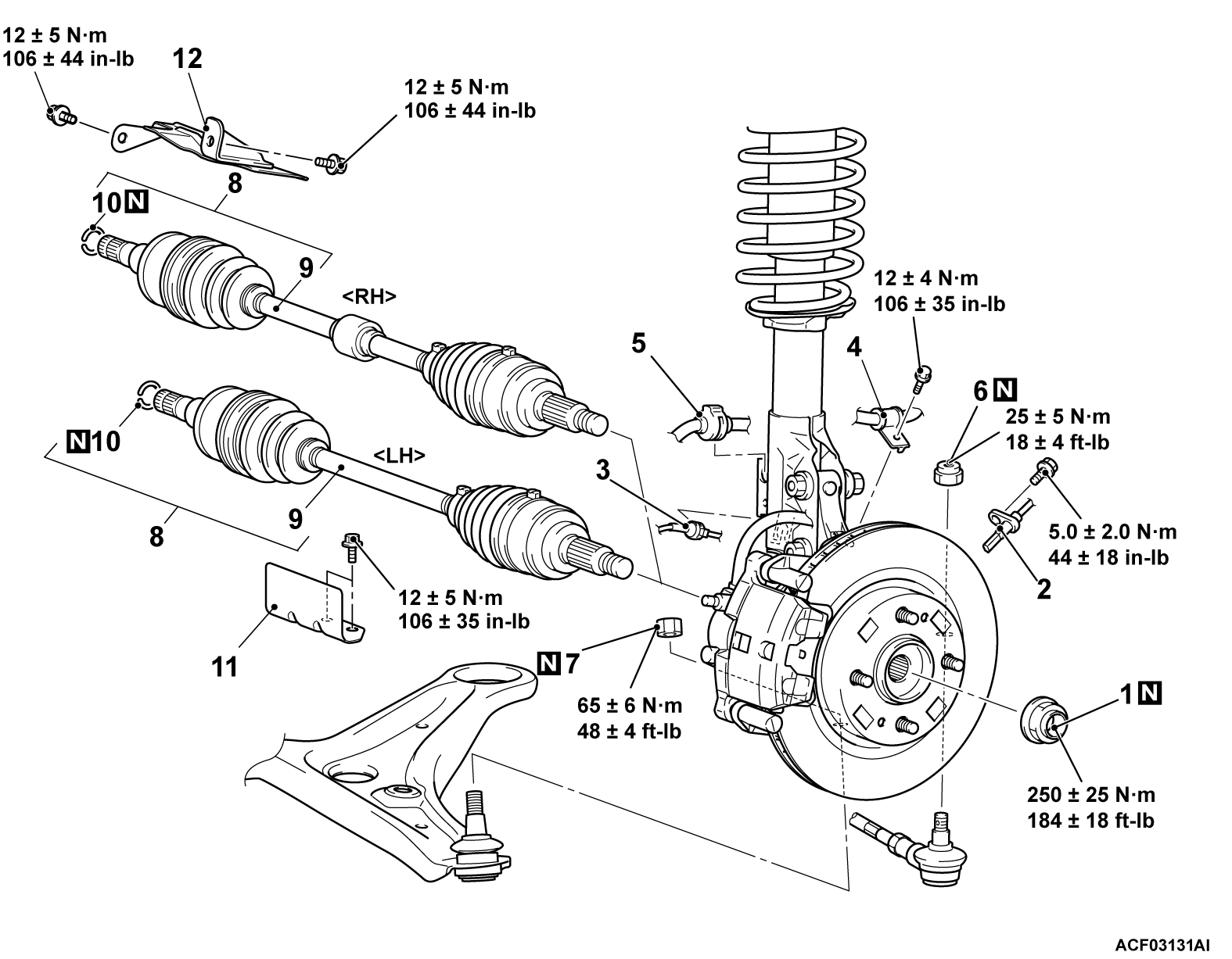
Driveshaft removal steps
<<A>>>>C<<1.Driveshaft nut
2.Front wheel speed sensor (Refer to GROUP 35C, Wheel Speed Sensor )
3.Front wheel speed sensor harness clamp
4.Brake hose clip
>>B<<5.Brake hose grommet
<<B>>6.Self-locking nut (tie rod end connection)
<<B>>7.Self-locking nut (lower arm ball joint connection)
<<C>>>>A<<8.Driveshaft assembly
9.Driveshaft
10.Circlip
Cover and heat protector removal steps
11.Front axle crossmember cover <CVT>
12.Front axle shaft heat protector
Required Special Tools:
  • MB992700: Lock Nut Chisel
  • MB990767: Front Hub and Flange Yoke Holder
  • MB991897 or MB992011: Ball Joint Remover
  • MB990241: Axle Shaft Puller
  • MB991000: Spacer
  • MB991017: Front Hub Removal and Installer
  • MB992867: Front Hub Remover and Installer Spacer
 
 
REMOVAL SERVICE POINTS
 
 
<<A>> DRIVESHAFT NUT REMOVAL
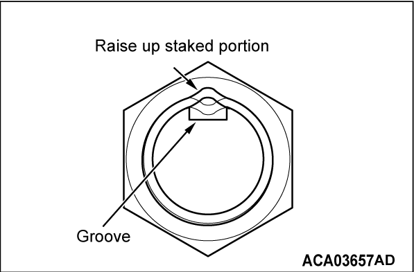
1. The staked portion of the driveshaft nut must face upwards.
2.
caution
  • Make sure that the lock nut chisel is set in the correct direction. Otherwise, the groove or thread in the driveshaft may be broken, or the tip of the chisel may be chipped.
  • Never use a chisel which tip is damaged.
  • For how to use the lock nut chisel, refer to the manufacturer's operating instructions.
Set the special tool MB992700 in the groove of the driveshaft with its "UPPER" mark facing upwards. Then strike the staked portion of the driveshaft nut with the chisel and a hammer to raise up.

3.
cautionBe careful not to damage the thread of the driveshaft.
Raise up the staked portion of the driveshaft nut until it does not interfere with the shaft thread.

4.
caution
  • Never use a impact wrench to loosen the driveshaft nut.
  • Do not apply the vehicle weight on the wheel bearing with the driveshaft nut loosened. Otherwise, the wheel bearing may be broken.
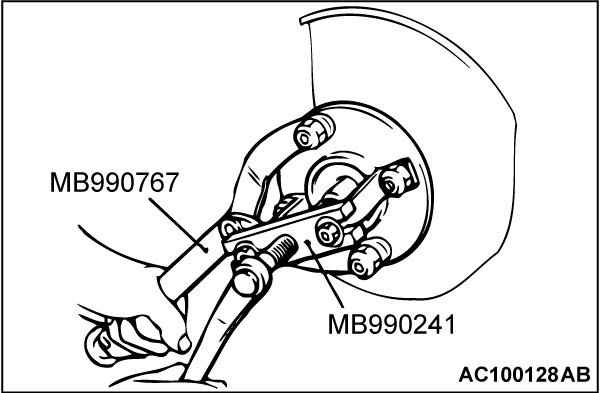
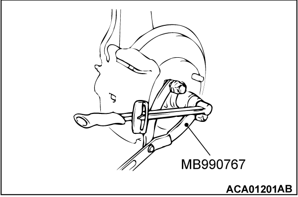
Use the special tool MB990767 to counter the hub as shown in the figure to remove the driveshaft nut.


<<B>> SELF-LOCKING NUT (TIE ROD END CONNECTION)/SELF-LOCKING NUT (LOWER ARM BALL JOINT CONNECTION) REMOVAL
caution
  • Do not remove the nut from ball joint. Loosen it and use special tool to avoid possible damage to ball joint threads.
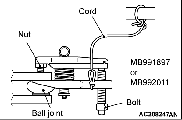
  • Hang special tool with cord to prevent it from falling.
1. Install the special tool MB991897 or MB992011 as shown in the figure.
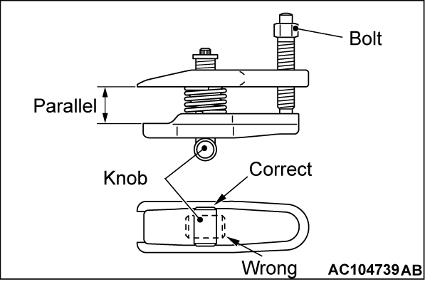
2. Turn the bolt and knob as necessary to make the jaws of special tool parallel, tighten the bolt by hand and confirm that the jaws are still parallel.
noteWhen adjusting the jaws in parallel, make sure the knob is in the position shown in the figure.
3. Tighten the bolt with a wrench to disconnect the tie rod end, lower arm ball joint.


<<C>> DRIVESHAFT ASSEMBLY REMOVAL
1.
caution
  • The magnetic encoder collects metallic particles easily, because it is magnetized. Make sure that the magnetic encoder does not collect metallic particles.
  • When removing the driveshaft, make sure that it does not contact with the magnetic encoder (integrated with the inner oil seal) to avoid damage.
If the driveshaft is seized with the hub, use the following special tools to push the driveshaft assembly out from the hub:
  • MB990241: Axle shaft puller
  • MB990767: Front hub & flange yoke holder
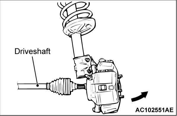
2. While pulling the lower side of the brake disc toward you, remove the driveshaft assembly from the hub.

3.
caution
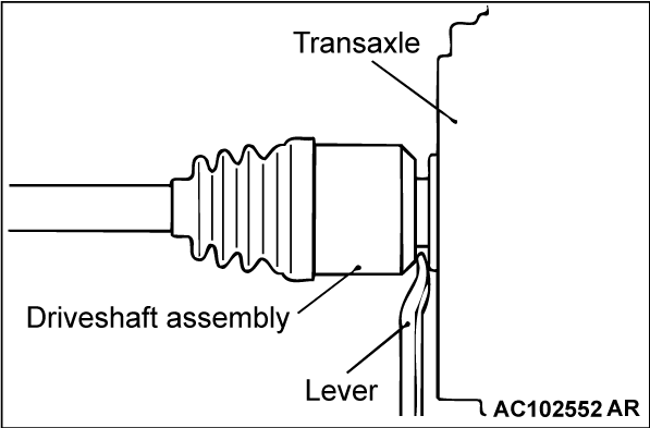
  • Never pull out the driveshaft assembly from the EBJ or VUJ assembly side. Otherwise, the ETJ assembly may be damaged. Always pull out from the ETJ side with a lever.
  • Care must be taken to ensure that the oil seal of the transaxle is not damaged by the spline part of the driveshaft assembly.
Insert a pry bar between the transaxle case and the driveshaft, and then pry and remove the driveshaft from the transaxle.
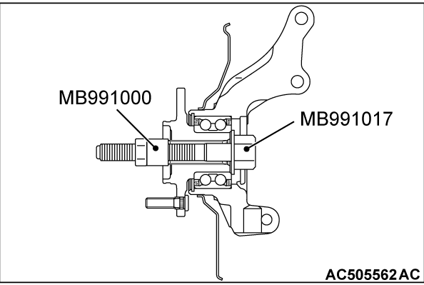
cautionDo not apply the vehicle weight to the wheel bearing with the driveshaft assembly removed. If, however, the vehicle weight shall be applied to the bearing (in order to move the vehicle), tighten the following special tools to the specified torque [270 ± 27 N·m (199 ± 20 ft-lb)]:
  • MB991000: Spacer
  • MB991017: Front hub removal and installer, except spacer (MB991019)


INSTALLATION SERVICE POINTS
 
 
>>A<< DRIVESHAFT ASSEMBLY INSTALLATION
caution
  • The magnetic encoder collects metallic particles easily, because it is magnetized. Make sure that the magnetic encoder should not collect metallic particles. Check that there is not any trouble prior to reassembling it.
  • When installing the driveshaft, make sure that it does not contact with the magnetic encoder (integrated with the inner oil seal) to avoid damage.
  • Care must be taken to ensure that the oil seal of the transaxle is not damaged by the spline part of the output shaft assembly or driveshaft assembly.


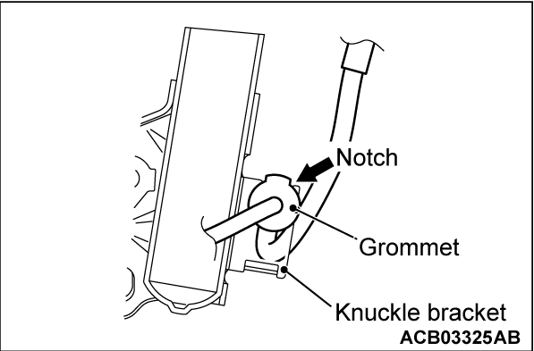
>>B<< BRAKE HOSE GROMMET INSTALLATION
Insert grommet to knuckle bracket securely as shown. The notch of grommet must be coincided with the top end of knuckle bracket.


>>C<< DRIVESHAFT NUT INSTALLATION
cautionDo not apply the vehicle weight on the front wheel hub assembly before fully tightening the driveshaft nut. Otherwise, the wheel bearing may be broken.
1. Check the hub seated surface for damage or corrosion. Whenever solvent is used for removing the corrosion, the surface should be degreased.
2. Check that the new driveshaft nut can be turned smoothly by hand. Then tighten it until it is seated.
3. Using the special tool MB990767, tighten the driveshaft nut.
Tightening torque: 250 ± 25 N·m (184 ± 18 ft-lb)
4. After tightening to the specified torque, check that the nut is seated securely.
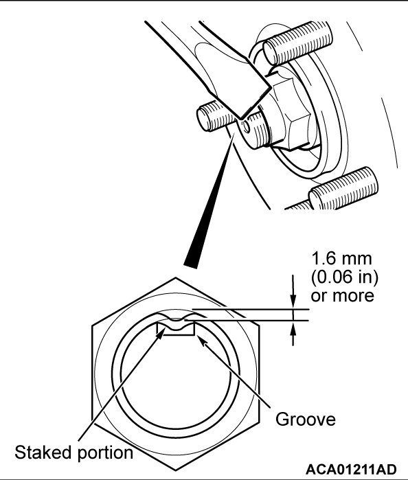
5. Use the chisel and a hammer to stake the nut until the center in the staked portion reaches the shown dimension.
6. Finally, check that the nut is not cracked at its staked portion.