DISASSEMBLY AND REASSEMBLY
|
|
- MD998375: Crankshaft front oil seal installer
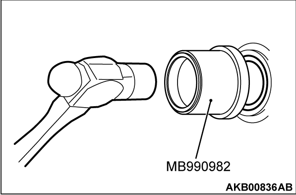
- MB990982: Roll stopper bush r & i arbor
Required Special Tools:
DISASSEMBLY SERVICE POINT
| caution |
|
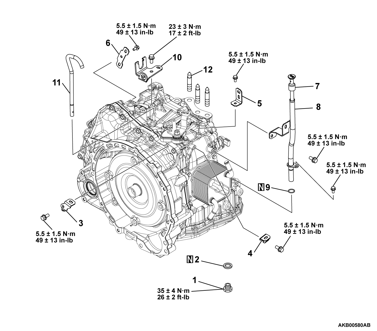
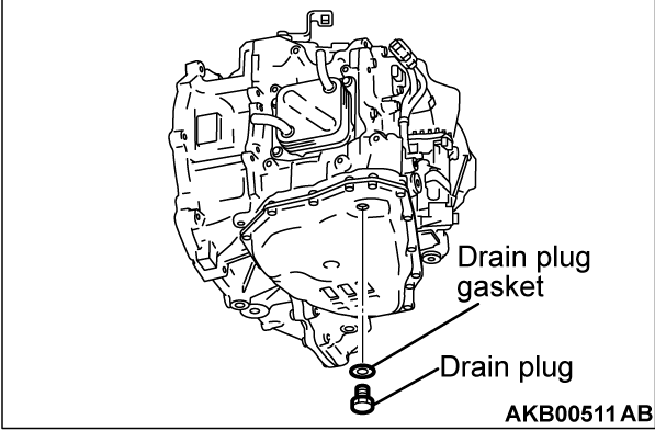
1. Remove the drain plug from the oil pan.
2. Remove the drain plug gasket from the drain plug.
3. Remove the harness bracket from the transaxle assembly.
4. Remove the oil filler tube and transmission fluid dipstick from the transaxle assembly.
5. Remove the control cable bracket and breather hose from the transaxle assembly.
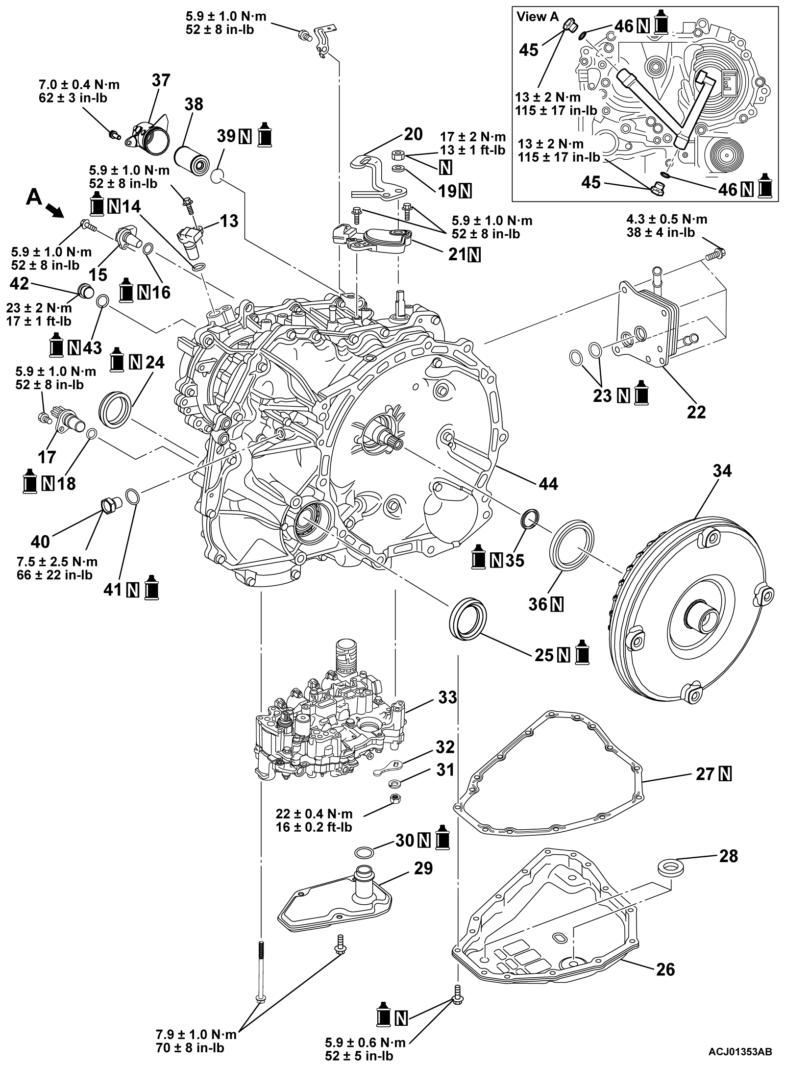
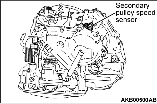
6. Remove the secondary pulley speed sensor from the transaxle assembly.
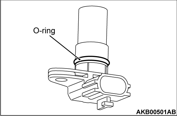
7. Remove the O-ring from the secondary pulley speed sensor.
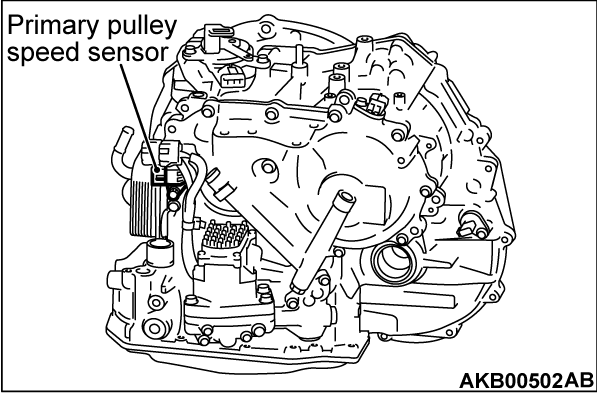
8. Remove the primary pulley speed sensor from the transaxle assembly.
9. Remove the O-ring from the primary pulley speed sensor.
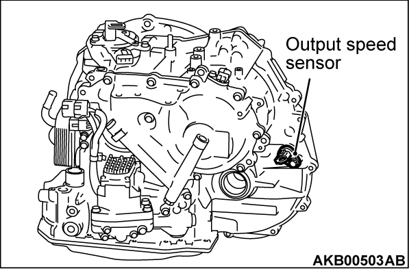
10. Remove the output speed sensor from the transaxle assembly.
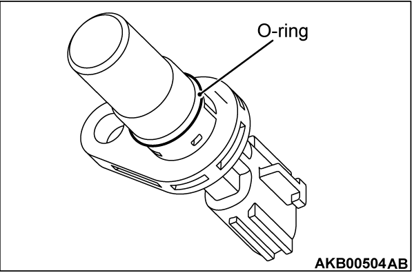
11. Remove the O-ring from the output speed sensor.
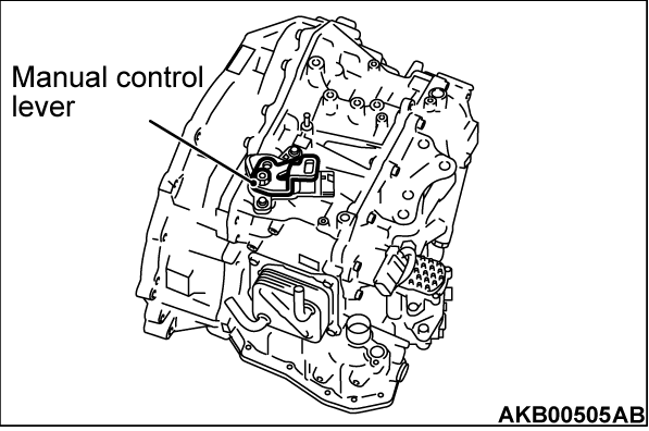
12. Remove the manual control lever from the manual shaft.
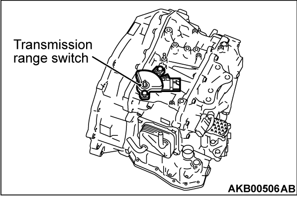
13. Remove the transmission range switch from the transaxle assembly.
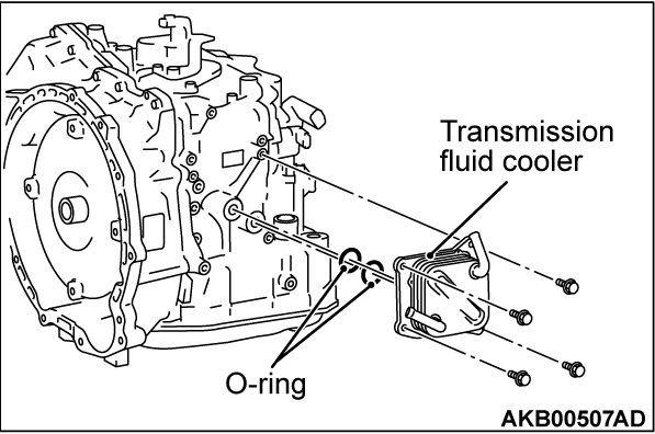
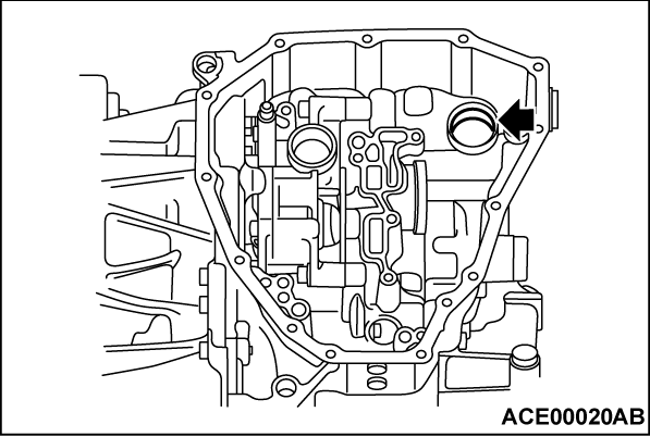
14. Remove the transmission fluid cooler from the transaxle assembly, and detach the O-ring from the transmission fluid cooler.
15.
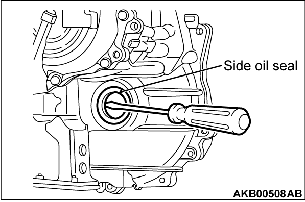
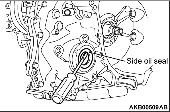
Using a flat-tipped screwdriver, remove the side oil seal from the transaxle assembly.
| caution | When removing the side oil seal, be careful not to cause damage to the transaxle assembly. |
16.
Using a flat-tipped screwdriver, remove the side oil seal from the transaxle assembly.
| caution | When removing the side oil seal, be careful not to cause damage to the transaxle assembly. |
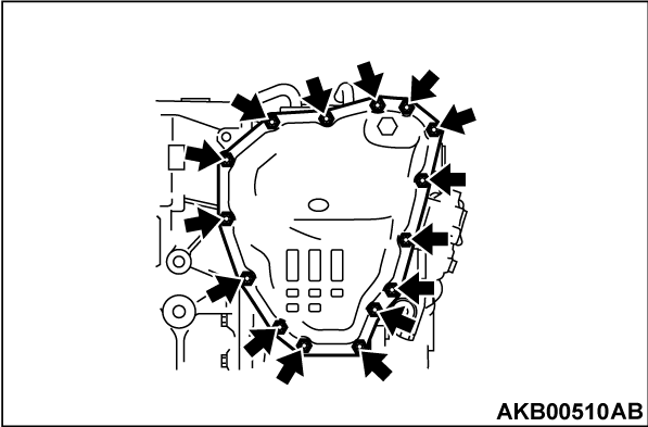
17. Remove the oil pan mounting bolts from the transaxle assembly.
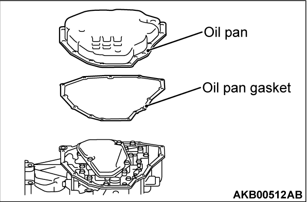
18. Remove the oil pan and oil pan gasket from the transaxle assembly.
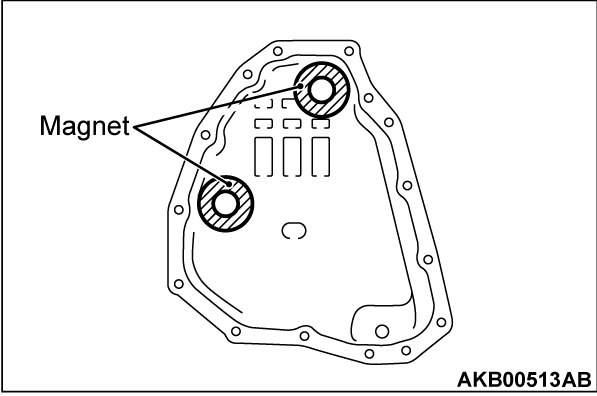
19. Remove the magnet from the oil pan.
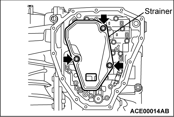
20. Remove the fluid strainer mounting bolts to remove the fluid strainer from the valve body assembly.
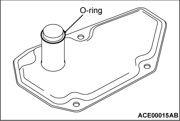
21. Remove the O-ring from the fluid strainer.
22.
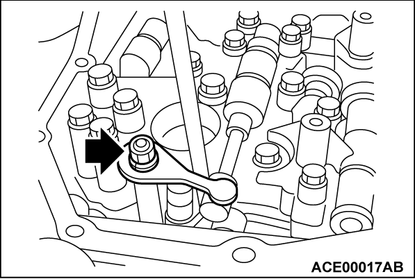
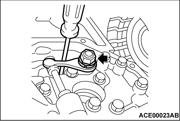
Remove the manual plate mounting nuts, and remove the manual plate and the spring washer from the manual shaft.
| caution |
|
23.
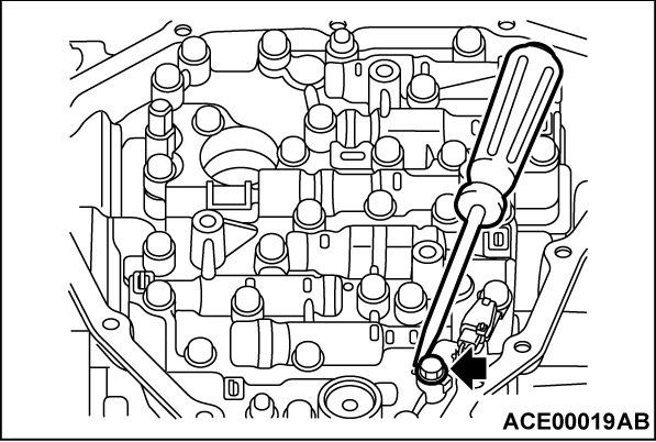
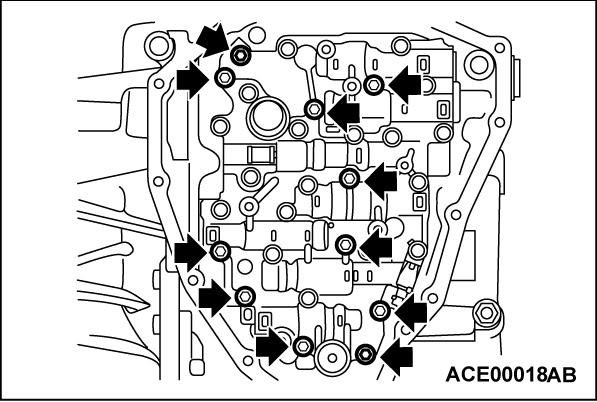
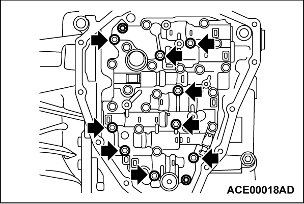
Remove the valve body assembly mounting bolts, and remove the valve body assembly.
| caution |
|
|
24.
| caution | To remove the torque converter, be careful not to scratch the bushing inside the sleeve. |
Remove the torque converter.
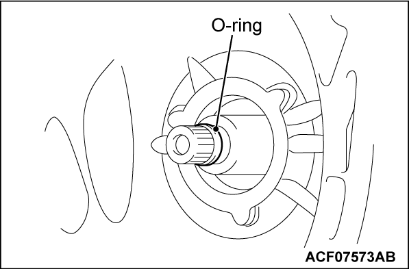
25. Remove the O-ring from the input shaft.
26.
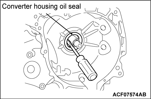
Use a flat-tipped screwdriver to remove the converter housing oil seal from the transaxle assembly.
| caution | To remove the converter housing oil seal, be careful not to scratch the converter housing and the input shaft. |
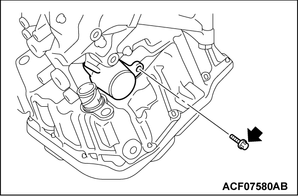
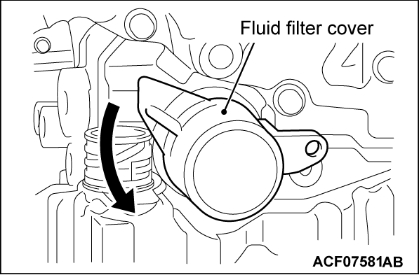
27. Remove the fluid filter cover mounting bolt.
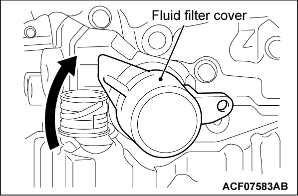
28. Rotate the fluid filter cover counterclockwise to remove it from the transaxle assembly.
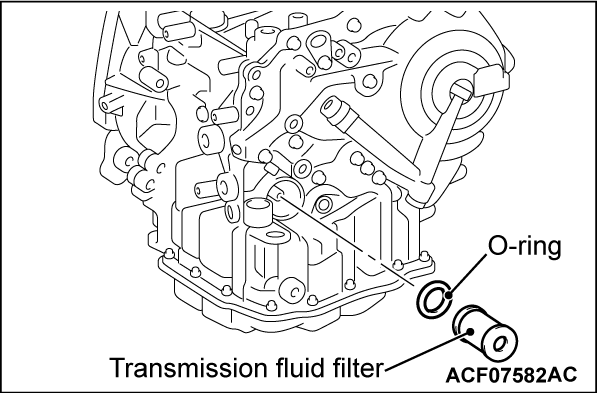
29. Remove the transmission fluid filter and the O-ring from the transaxle assembly.
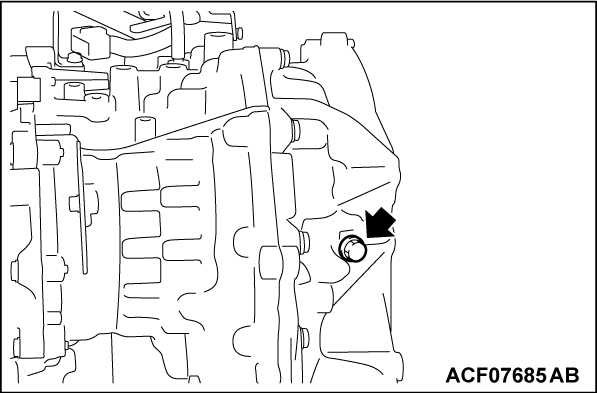
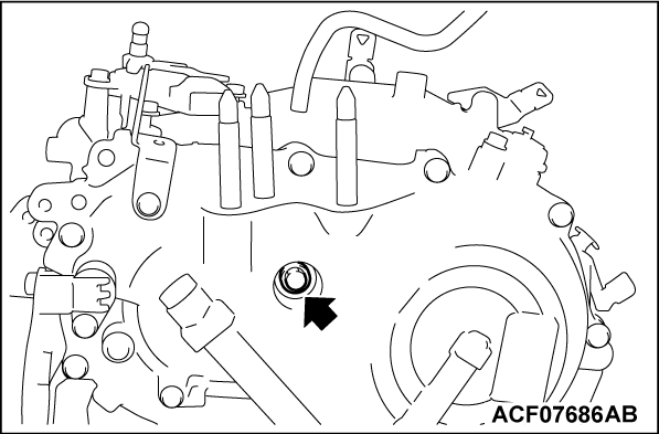
30. Remove the plug from the transaxle assembly.
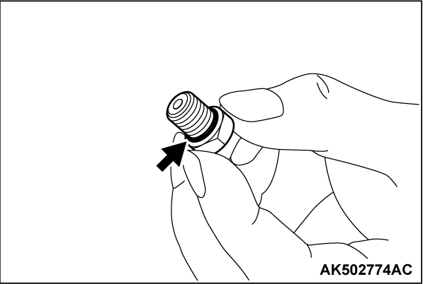
31. Remove the O-ring from the plug.
32. Remove the plug from the transaxle assembly.
33. Remove the O-ring from the plug.
ASSEMBLY SERVICE POINT
1.
Install the O-ring to the plug.
| caution |
|
2. Tighten the plug to the specified torque.
Tightening torque:
23 ± 2 N·m (17 ± 1 ft-lb)
3.
Install the O-ring to the plug.
| caution |
|
4. Tighten the plug to the specified torque.
Tightening torque:
7.5 ± 2.5 N·m (66 ± 22 in-lb)
5.
Install the transmission fluid filter and the O-ring to the transaxle assembly.
| caution |
|
6. Install the fluid filter cover to the transaxle assembly, and then rotate it clockwise to secure it.
7. Tighten the fluid filter cover mounting bolt to the specified torque.
Tightening torque:
7.0 ± 0.4 N·m (62 ± 3 in-lb)
8.
| caution |
|
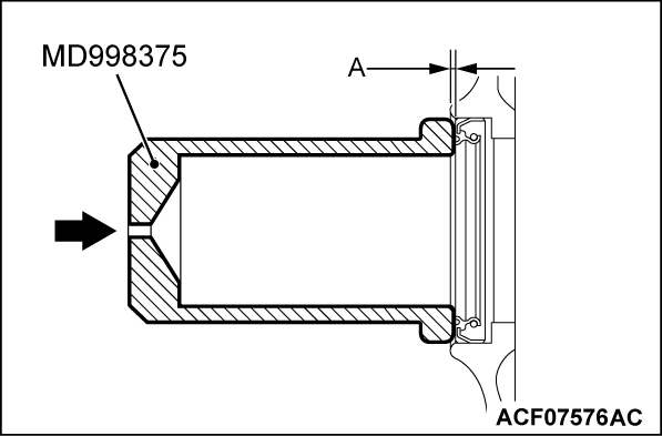
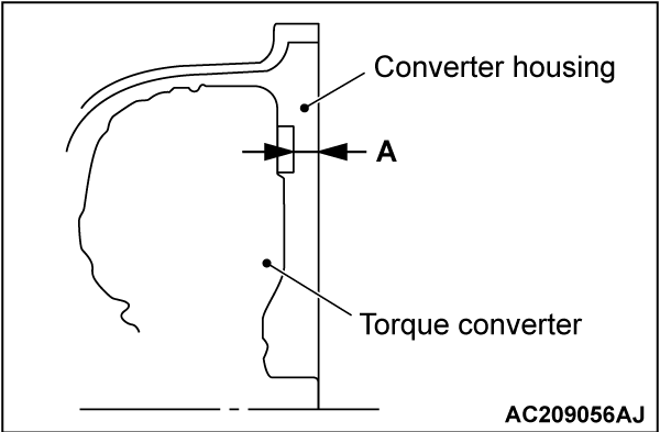
Apply the transmission fluid around the circumference of the converter housing oil seal. Then use the special tool MD998375 to install the converter housing oil seal so that the dimension (A) shown meets the standard value.
Standard value (A): 1.3 ± 0.5 mm (0.05 ± 0.02 inch)
9.
Install the O-ring to the input shaft.
| caution |
|
10.
| caution |
|
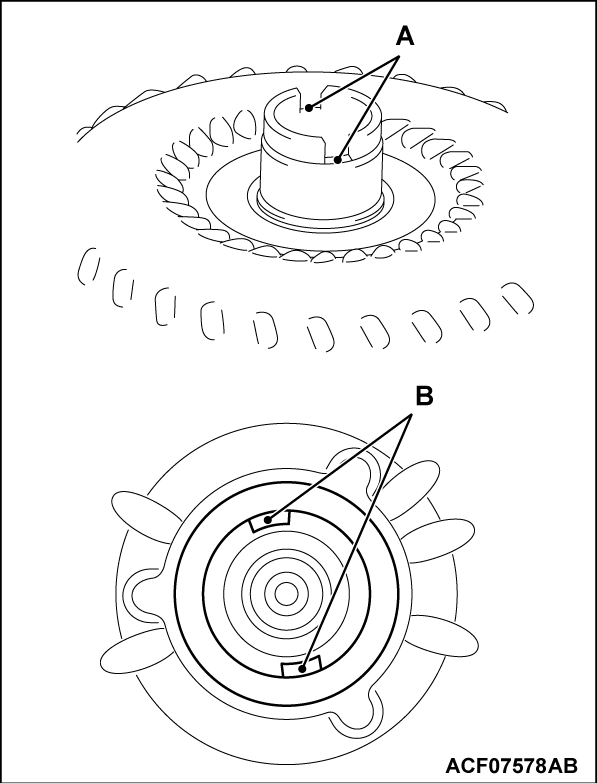
Align (A) on the torque converter with the (B) on the drive sprocket at the transaxle assembly.
11.
The dimension (A) should meet the standard value.
| caution | Measure at two points or more to determine an average value. |
Standard value (A): approximately 12.2 mm (0.48 inch)
12. Apply the transmission fluid to the terminal assembly mount on the transaxle assembly.
13.
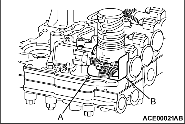
The wire (A) on the terminal assembly should not be trapped in the terminal assembly bracket (B).
| caution | When the wire(s) on the valve body assembly are pinched, loose or twisted, correct them. |
14.
| caution |
|
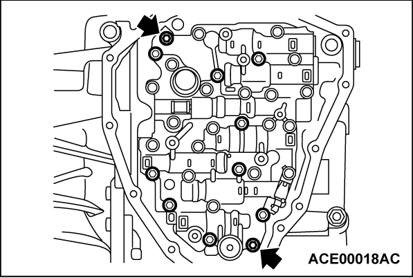
Install the valve body assembly to the transaxle assembly.
15. Tighten the two mounting bolts by hand.
|
16. Then tighten nine mounting bolts by hand.
|
17. Tighten 11 bolts to the specified torque.
Tightening torque:
7.9 ± 1.0 N·m (70 ± 8 in-lb)
18.
Install the manual plate and the spring washer, and tighten the mounting nuts to the specified torque.
| caution |
|
Tightening torque:
22 ± 0.4 N·m (16 ± 0.2 ft-lb)
19.
Install the O-ring to the fluid strainer.
| caution |
|
20.
Install the fluid strainer to the valve body assembly, and then tighten the mounting bolts to the specified torque.
| caution | The fluid strainer should butt tight to the valve body. |
|
Tightening torque:
7.9 ± 1.0 N·m (70 ± 8 in-lb)
21. Install the magnet on the oil pan.
22.
Install the oil pan and oil pan gasket on the transaxle assembly.
| caution | Do not re-use the oil pan gasket. |
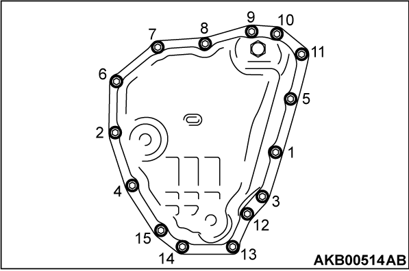
23. Tighten the front oil pan mounting bolts by hand.
24. Tighten the oil pan mounting bolts to the specified torque in the order shown.
Tightening torque:
5.9 ± 0.6 N·m (52 ± 5 in-lb)
25.
Using the special tool MB990982, install the side oil seal on the transaxle assembly.
| caution |
|
Depth from the case edge: within - 1.8 ± 0.5 mm (0.07 ± 0.02 inch) (recessed).
26.
Using the special tool MB990982, install the side oil seal on the transaxle assembly.
| caution |
|
Depth from the case edge: within - 1.8 ± 0.5 mm (0.07 ± 0.02 inch) (recessed).
27.
Install the O-ring on the transmission fluid cooler.
| caution |
|
28. Install the transmission fluid cooler on the transaxle assembly, and tighten the mounting bolts to the specified torque.
Tightening torque:
4.3 ± 0.5 N·m (38 ± 4 in-lb)
29.
| caution | Do not re-use the transmission range switch. |
Install the transmission range switch on the transaxle assembly as shown.
30. Install the transmission range switch on the transaxle assembly.
31. Tighten the transmission range switch mounting bolts by hand.
32. Install the manual control lever on the manual shaft.
33. Install the washer on the manual shaft, and tighten the mounting nut to the specified torque.
Tightening torque:
17 ± 2 N·m (13 ± 1 ft-lb)
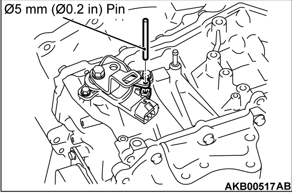
34. Set the manual shaft at N position.
35. Insert a Φ5 mm (Φ0.2 inch) pin through the hole on the manual control lever down to the recess on the transmission range switch to align the transmission range switch.
36.
| caution | The pin should be engaged fully into the recess on the transmission range switch. |
Tighten the transmission range switch mounting bolts to the specified torque.
Tightening torque:
5.9 ± 1.0 N·m (52 ± 8 in-lb)
37. Remove the pin.
38.
Install the O-ring on the output speed sensor.
| caution |
|
39. Install the output speed sensor on the transaxle assembly, and tighten the mounting bolt to the specified torque.
Tightening torque:
5.9 ± 1.0 N·m (52 ± 8 in-lb)
40.
Install the O-ring on the primary pulley speed sensor.
| caution |
|
41. Install the primary pulley speed sensor on the transaxle assembly, and tighten the mounting bolt to the specified torque.
Tightening torque:
5.9 ± 1.0 N·m (52 ± 8 in-lb)
42.
Install the O-ring on the secondary pulley speed sensor.
| caution |
|
43. Install the secondary pulley speed sensor on the transaxle assembly, and tighten the mounting bolt to the specified torque.
Tightening torque:
5.9 ± 1.0 N·m (52 ± 8 in-lb)
44.
The dimension (A) should meet the standard value.
| caution | Measure at two or more points to determine an average value. |
Standard value (A): approximately 12.2 mm (0.48 inch)
45. Install the control cable bracket and breather hose on the transaxle assembly.
46. Install the harness bracket on the transaxle assembly.
47.
| caution |
|
Install the oil filler tube and transmission fluid dipstick on the transaxle assembly.
48.
Install the drain plug and drain plug gasket on the transaxle assembly, and tighten to the specified torque.
| caution | Do not re-use the drain plug gasket. |
Tightening torque:
35 ± 4 N·m (26 ± 2 ft-lb)
![[Previous]](../../../buttons/fprev.png)
![[Next]](../../../buttons/fnext.png)

