REMOVAL AND INSTALLATION
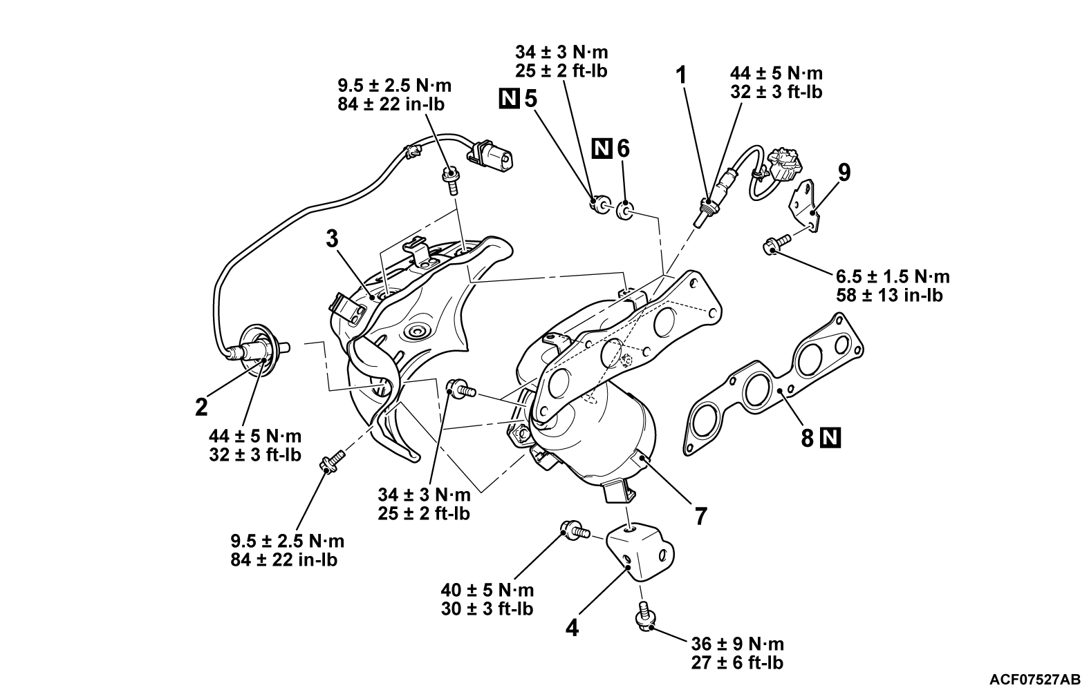
Pre-removal Operation | Post-installation Operation |
Required Special Tools:
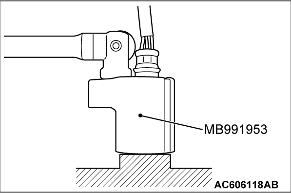
- MB991953: Oxygen Sensor Wrench
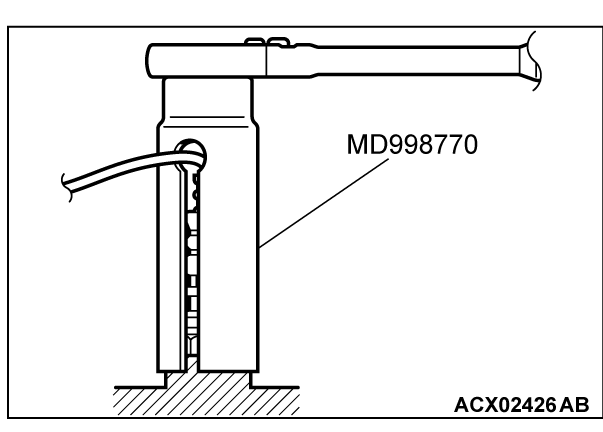
- MD998770: Oxygen Sensor Wrench
REMOVAL SERVICE POINTS
<<A>> HEATED OXYGEN SENSOR (REAR) REMOVAL
1. Remove the heated oxygen sensor (rear) connector connection and harness clip.
2. Use special tool MB991953 to remove the heated oxygen sensor (rear).
<<B>> LINEAR AIR-FUEL RATIO SENSOR REMOVAL
Use the special tool MD998770 to remove the linear air-fuel ratio sensor.
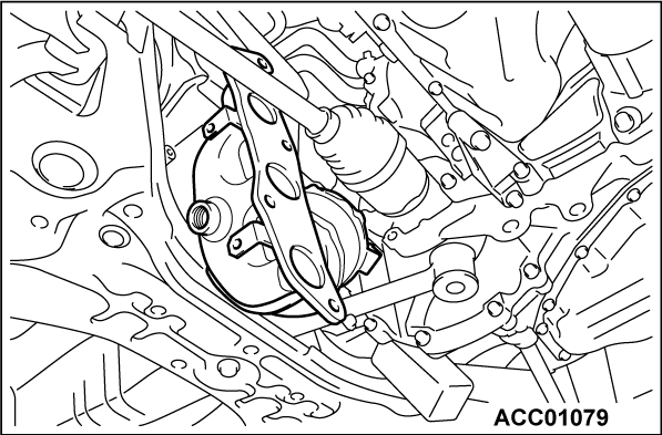
<<C>> ENGINE ROLL STOPPER ROD ASSEMBLY DISCONNECTION
Disconnect the engine roll stopper rod assembly at the transaxle in order to allow sufficient clearance to remove and install the exhaust manifold.
INSTALLATION SERVICE POINTS
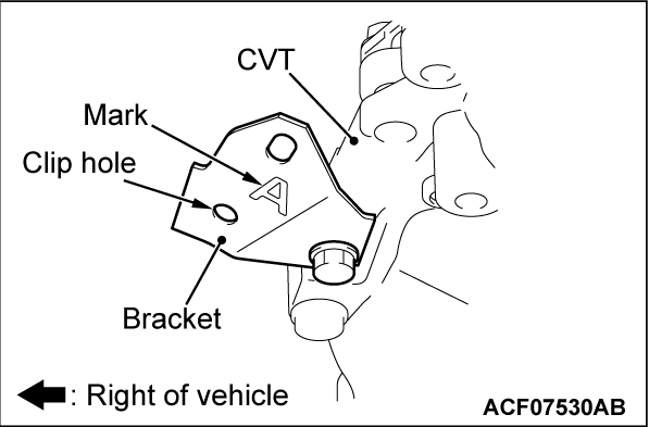
>>A<< BRACKET INSTALLATION
1. Position the bracket as shown and tighten it to the specified torque.
Tightening torque: 6.5 ± 1.5 N·m (58 ± 13 in-lb)
>>B<< LINEAR AIR-FUEL RATIO SENSOR INSTALLATION
1. In the same manner as removal, use the special tool MD998770 to tighten the linear air-fuel ratio sensor to the specified torque.
Tightening torque: 44 ± 5 N·m (32 ± 3 ft-lb)
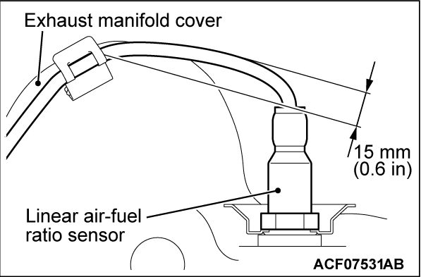
2. Install the linear air-fuel ratio sensor connector connection and harness clip.
3. Route the linear air-fuel ratio sensor wire as shown.
>>C<< HEATED OXYGEN SENSOR (REAR) INSTALLATION
1. In the same manner as removal, use special tool MB991953 to tighten the heated oxygen sensor (rear) to the specified torque.
Tightening torque: 44 ± 5 N·m (32 ± 3 ft-lb)
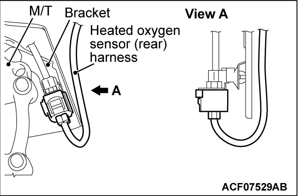
2. Install the heated oxygen sensor (rear) connector connection and harness clip.
3. Route the heated oxygen sensor (rear) wire as shown <M/T>.
![[Previous]](../../../buttons/fprev.png)
![[Next]](../../../buttons/fnext.png)

