DTC P011B: Engine Coolant Temperature /Intake Air Temperature Correlation
CIRCUIT OPERATION
TECHNICAL DESCRIPTION
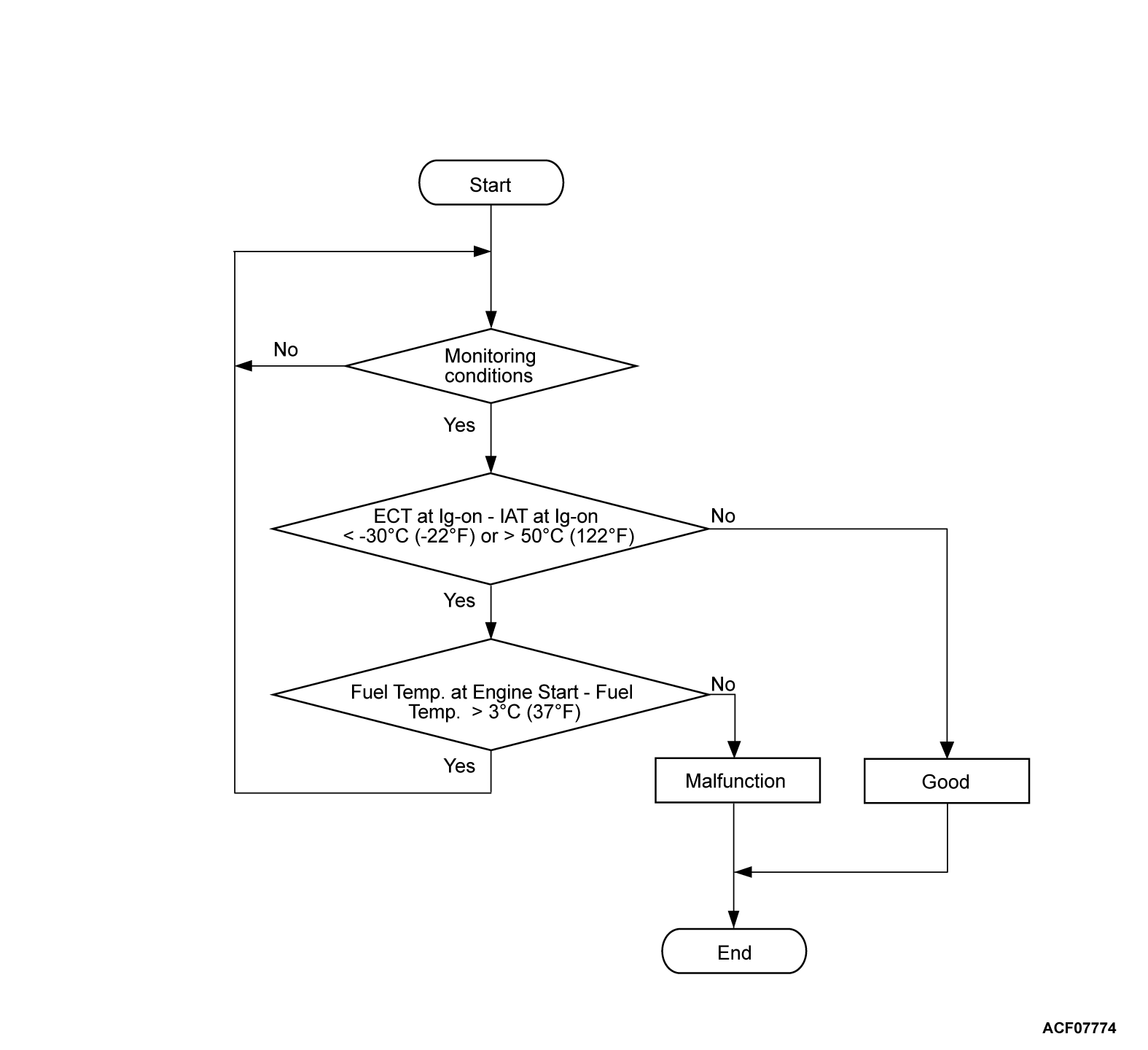
DESCRIPTIONS OF MONITOR METHODS
- Intake air temperature sensor output voltage does not change when specified go/stop operations are repeated.
MONITOR EXECUTION
- Once per driving cycle
MONITOR EXECUTION CONDITIONS (Other monitor and Sensor)
Other Monitor (There is no temporary DTC set in memory for the item monitored below)
- Not applicable
Sensor (The sensor below is determined to be normal)
- Engine coolant temperature sensor
- Intake air temperature sensor
Check Conditions
- The engine coolant temperature is higher than 78°C (172°F) engine stop in previous Drive Cycle
- The engine coolant temperature - fuel tank temperature is between -5°C (23°F) and 5°C (41°F) when the ignition on.
- Battery positive voltage is higher than 10 volts.
- The fuel tank temperature when ignition on - fuel tank temperature* is 3°C (37°F) or more when the engine is started.
| note | *: Fuel tank temperature until 600 seconds accumulated with Vehicle Speed 25mph(40km/h) or more. |
Judgment Criterion
- The engine coolant temperature - intake air temperature is less than -30°C (-22°F) or greater than 50°C (122°F) when the ignition on.
FAIL-SAFE AND BACKUP FUNCTION
- None
TROUBLESHOOTING HINTS (The most likely causes for this code to be set are:)
- Engine coolant temperature sensor failed.
- Engine coolant temperature sensor circuit harness damage, or connector damage.
- Intake air temperature sensor failed.
- Intake air temperature sensor circuit harness damage, or connector damage.
- ECM failed.
DIAGNOSIS
Required Special Tools:
- MB992744: Vehicle Communication Interface-Lite (V.C.I.-Lite)
- MB992745: V.C.I.-Lite Main Harness A
- MB992747: V.C.I.-Lite USB Cable Short
- MB992748: V.C.I.-Lite USB Cable Long
- MB991958: Scan Tool (M.U.T.-III Sub Assembly)
- MB991824: Vehicles Communication Interface (V.C.I.)
- MB991827: M.U.T.-III USB Cable
- MB991910: M.U.T.-III Main Harness A (Vehicles with CAN communication system)
STEP 1. Using scan tool (M.U.T.-III), check data list item 5: Intake Air Temperature Sensor.
| caution | To prevent damage to scan tool (M.U.T.-III), always turn the ignition switch to the "LOCK" (OFF) position before connecting or disconnecting scan tool (M.U.T.-III). |
(2) Remove the mass air flow sensor from the air intake hose.
(3) Turn the ignition switch to the "ON" position.
(4) Set scan tool (M.U.T.-III) to the data reading mode for item 5, Intake Air Temperature Sensor.
(5) Heating the sensor using a hair drier.
- The indicated temperature increases.
note Do not allow it to increase over 80°C (176°F).
(6) Turn the ignition switch to the "LOCK" (OFF) position.
(7) Attach the mass air flow sensor.
Is the sensor operating properly?
STEP 2. Check the intake air temperature sensor.
STEP 3. Check the continuity at intake air temperature sensor harness side connector.
(1) Disconnect the mass intake volume air flow sensor connector and measure at the harness side.
(2) Check for the continuity between terminal AFSE line and ground.
- Continuity (2 ohms or less)
Does continuity exist?
STEP 4. Check for harness damage in ATS line between intake volume air flow sensor connector and ECM connector.
Is the harness wire in good condition?
STEP 5. Check for harness damage in AFSE line between intake volume air flow sensor connector and ECM connector.
Is the harness wire in good condition?
STEP 6. Using scan tool (M.U.T.-III), check data list item 5: Intake Air Temperature Sensor.
(1) Turn the ignition switch to the "ON" position.
(2) Set scan tool (M.U.T.-III) to the data reading mode for item 5, Intake Air Temperature Sensor.
- The intake air temperature and temperature shown with the scan tool should approximately match.
(3) Turn the ignition switch to the "LOCK" (OFF) position.
Is the sensor operating properly?
STEP 7. Using scan tool (M.U.T.-III), check data list item 6: Engine Coolant Temperature Sensor.
| caution | To prevent damage to scan tool (M.U.T.-III), always turn the ignition switch to the "LOCK" (OFF) position before connecting or disconnecting scan tool (M.U.T.-III). |
(2) Turn the ignition switch to the "ON" position.
(3) Set scan tool (M.U.T.-III) to the data reading mode for item 6, Engine Coolant Temperature Sensor.
- The engine coolant temperature and temperature shown with the scan tool should approximately match.
(4) Turn the ignition switch to the "LOCK" (OFF) position.
Is the sensor operating properly?
STEP 8. Check the engine coolant temperature sensor.
STEP 9. Check the continuity at engine coolant temperature sensor harness side connector.
(1) Disconnect the engine coolant temperature sensor connector and measure at the harness side.
(2) Check for the continuity between terminal SENG line and ground.
- Continuity (2 ohms or less)
Does continuity exist?
STEP 10. Check of harness damage in WTS line between engine coolant temperature sensor connector and ECM connector.
Is the harness wire in good condition?
STEP 11. Check of harness damage in SENG line between engine coolant temperature sensor connector and ECM connector.
Is the harness wire in good condition?
STEP 12. Using scan tool (M.U.T.-III), check data list item 6: Engine Coolant Temperature Sensor.
(1) Turn the ignition switch to the "ON" position.
(2) Set scan tool (M.U.T.-III) to the data reading mode for item 6, Engine Coolant Temperature Sensor.
- The engine coolant temperature and temperature shown with the scan tool should approximately match.
(3) Turn the ignition switch to the "LOCK" (OFF) position.
Is the sensor operating properly?
![[Previous]](../../../buttons/fprev.png)
![[Next]](../../../buttons/fnext.png)


