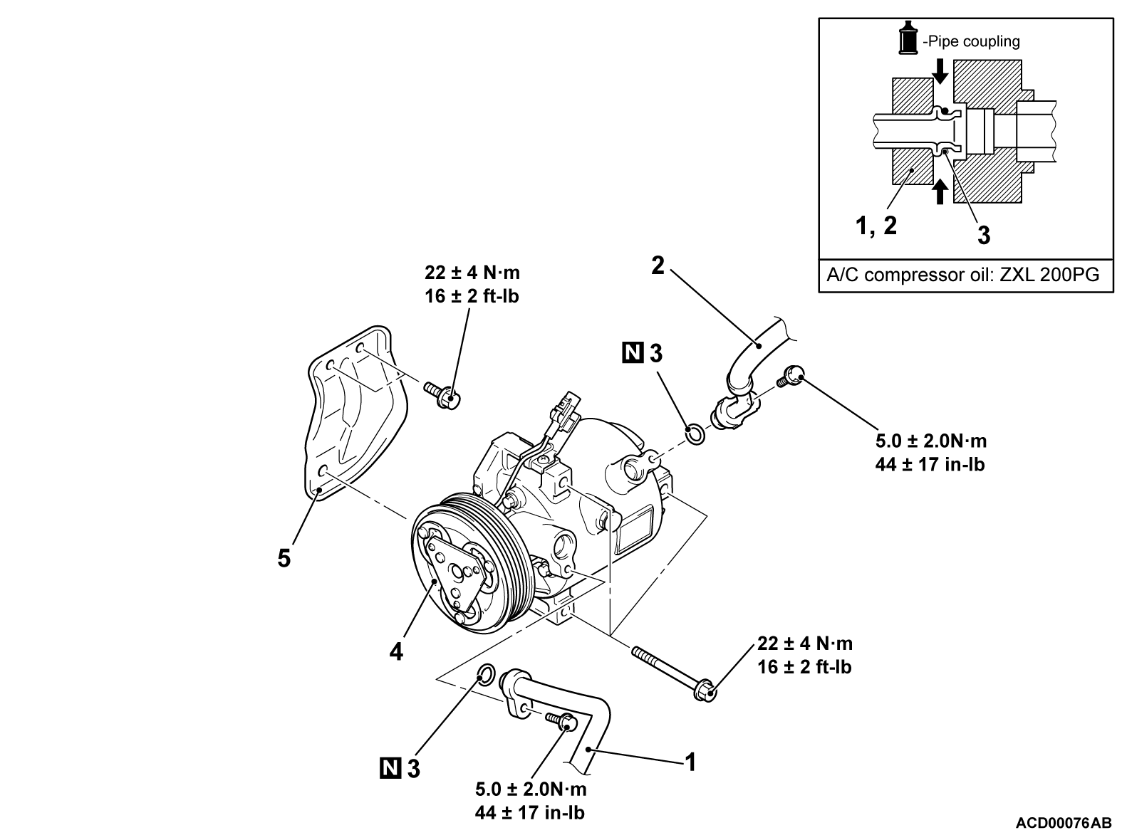
REMOVAL AND INSTALLATION
| caution |
|
Pre-removal operation | Post-installation Operation |
| note | The service points which are not described are the same as before. |
REMOVAL SERVICE POINTS
<<A>> DISCHARGE FLEXIBLE HOSE/SUCTION FLEXIBLE HOSE DISCONNECTION
| caution | Use the plug which is not breathable because A/C compressor oil or receiver have high hygroscopicity. |
Plug the hose nipple removed to prevent the entry of dust and dirt.
<<B>> A/C COMPRESSOR AND CLUTCH ASSEMBLY REMOVAL
Be careful not to spill the A/C compressor oil and remove the A/C compressor.
INSTALLATION SERVICE POINT
>>A<< A/C COMPRESSOR AND CLUTCH ASSEMBLY INSTALLATION
If a new compressor is installed, first adjust the amount of oil according to the procedures described below, and then install the compressor.
1. Measure the amount X mL (x fl.oz) of oil within the removed compressor.
2. Drain (from the new compressor) the amount of oil calculated according to the following formula, and then install the new compressor.
New compressor oil amount = 60mL (2.0 fl.oz)
60 mL (2.0 fl.oz) - X mL (x fl.oz) = Y mL (y fl.oz)
| note | Y mL indicates the amount of oil in the refrigerant line, the condenser, the evaporator, etc. |
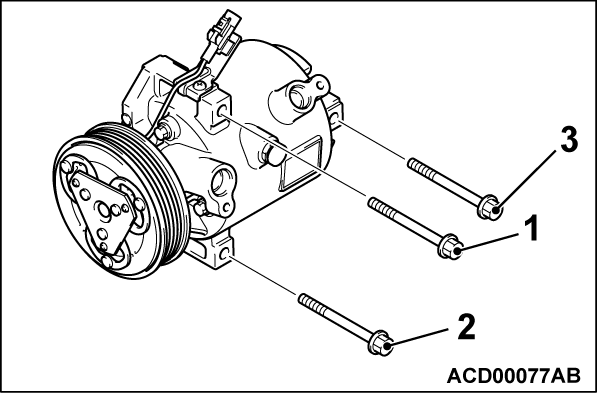
3. Tighten A/C compressor assembly mounting bolts to the specified torque in the order of number shown in the figure.
Tightening torque: 22 ± 4 N·m (16 ± 2 ft-lb)
![[Previous]](../../../buttons/fprev.png)
![[Next]](../../../buttons/fnext.png)


