Inspection Procedure 2: Vehicle power does not turn ON. (not possible with both of power supply mode ACC and ON)
| caution | Before replacing the ECU, ensure that the power supply circuit, the ground circuit and the communication circuit are normal. |
TECHNICAL DESCRIPTION (COMMENT)
When the vehicle power does not turn ON (not possible with both of power supply mode ACC and ON), the battery, CAN bus line, OSS-ECU, OSS-ECU power supply, or ground circuit may have a problem.
| note | OSS-ECU can communicate with the scan tool (M.U.T.-III) even when the engine switch is in the "OFF" position. |
TROUBLESHOOTING HINTS
- Malfunction of battery
- Damaged wiring harness and connectors
- Malfunction of engine switch (poor connector contact, poor engine switch contact)
- Malfunction of the CAN bus line
- Malfunction of ETACS-ECU
- Malfunction of OSS-ECU
DIAGNOSIS
STEP 1. Battery check
Perform the battery test to check the battery status. (Refer to GROUP 54A - Battery  .)
.) Replace the battery.
 .)
.)Is the check result normal?
 Replace the battery.
STEP 2. Using scan tool (M.U.T.-III), communicates with this system.
Check that the communication with scan tool (M.U.T.-III) is possible.
| note | If ETACS-ECU is not active, OSS-ECU cannot communicate with the scan tool (M.U.T.-III). |
(1)
| caution | To prevent damage to scan tool (M.U.T-III), always turn the power supply mode of the engine switch to the OFF position before connecting or disconnecting scan tool (M.U.T-III). |
(2) Turn the power supply mode of the engine switch to ON.
(3) Open the driver’s side door.
(4) Check that OSS-ECU can communicate with the scan tool (M.U.T.-III).
(5) Turn the power supply mode of the engine switch to OFF.
Is the check result normal?
STEP 3. Using scan tool (M.U.T-III), diagnose the CAN bus line.
(1)
| caution | To prevent damage to scan tool (M.U.T-III), always turn the power supply mode of the engine switch to the OFF position before connecting or disconnecting scan tool (M.U.T-III). |
(2) Turn the power supply mode of the engine switch to ON.
(3) Diagnose the CAN bus line.
(4) Turn the power supply mode of the engine switch to OFF.
Is the CAN bus line found to be normal?
STEP 4. Using scan tool (M.U.T.-III), read the diagnostic trouble code.
Check if the diagnosis trouble code is stored in the OSS-ECU.
(1)
| caution | To prevent damage to scan tool (M.U.T.-III), always turn the power supply mode of the engine switch to the OFF position before connecting or disconnecting scan tool (M.U.T.-III). |
(2) Turn the power supply mode of the engine switch to ON.
(3) Check if DTC is stored.
(4) Turn the power supply mode of the engine switch to OFF.
Is the DTC stored?
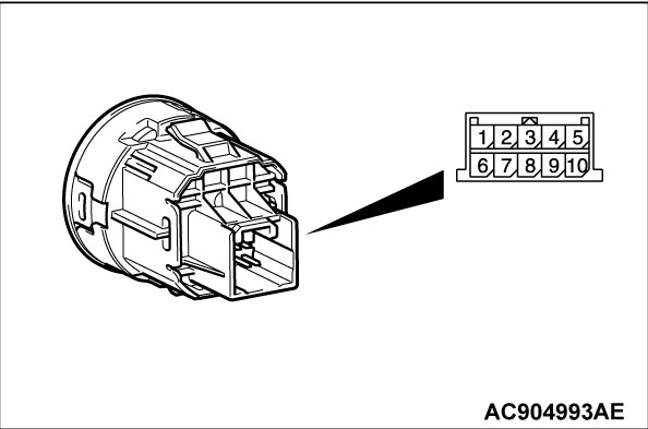
STEP 5. Engine switch check
Continuity check of engine switch.
 Replace the engine switch.
|
Is the check result normal?
 Replace the engine switch.
![[Previous]](../../../buttons/fprev.png)
![[Next]](../../../buttons/fnext.png)

