DTC B1130: Ignition power supply
| caution |
|
DTC SET CONDITION
If the output power supply status is different from the engine switch status information received from ETACS-ECU via CAN, OSS-ECU stores DTC B1130. At the same time, OSS-ECU displays the power supply system error warning to the combination meter, and flashes the indicator of engine switch in orange.
TECHNICAL DESCRIPTION (COMMENT)
Check Conditions
- The terminal voltage of +B1 and +B2 is between 10 and 16 V.
Judgment Criterion
- Any of the following conditions is met, and 2 seconds or more have elapsed.
- The engine switch status information received from ETACS-ECU is other than OFF when the power supply mode of OSS is OFF.
- The engine switch status information received from ETACS-ECU is other than ACC when the power supply mode of OSS is ACC.
- The engine switch status information received from ETACS-ECU is other than ON when the power supply mode of OSS is ON.
- IG2M is Hi with the OSS power supply mode OFF
- IG2M is Hi with the OSS power supply mode ACC
- IG2M is Lo with the OSS power supply mode ON
TROUBLESHOOTING HINTS
- Malfunction of the CAN bus line
- Damaged wiring harness or connector (short to ground, short to power supply, or open circuit in ACC line, IG1 line, IG2 line or IGM2 line)
- Malfunction of ACC relay
- Malfunction of IG1 relay
- Malfunction of IG2 Relay
- Malfunction of OSS-ECU
- Malfunction of ETACS-ECU
- Commercial electric products that are connected to the accessory socket
note Be sure to remove the commercial electric products that are connected to the accessory socket before troubleshooting. Otherwise troubleshooting cannot be performed correctly.
DIAGNOSIS
STEP 1. Using scan tool (M.U.T-III), diagnose the CAN bus line.
(1)
| caution | To prevent damage to scan tool (M.U.T-III), always turn the power supply mode of the engine switch to the OFF position before connecting or disconnecting scan tool (M.U.T-III). |
(2) Turn the power supply mode of the engine switch to ON.
(3) Diagnose the CAN bus line.
(4) Turn the power supply mode of the engine switch to OFF.
Is the CAN bus line found to be normal?
STEP 2. Using scan tool (M.U.T.-III), read the diagnostic trouble code.
(1)
| caution | To prevent damage to scan tool (M.U.T.-III), always turn the power supply mode of the engine switch to the OFF position before connecting or disconnecting scan tool (M.U.T.-III). |
(2) Turn the power supply mode of the engine switch to ON.
(3) Check if OSS-ECU DTC B1133 is stored.
(4) Turn the power supply mode of the engine switch to OFF.
Is the DTC stored?
STEP 3. Using scan tool (M.U.T.-III), check data list.
(1)
| caution | To prevent damage to scan tool (M.U.T.-III), always turn the power supply mode of the engine switch to the OFF position before connecting or disconnecting scan tool (M.U.T.-III). |
(2) Turn the power supply mode of the engine switch to OFF.
(3) Operate the engine switch to change the power supply mode, and check that the data list display of ETACS-ECU is changed.
- When power supply mode is ACC or ON.
| ||||||||||
- When power supply mode is ON or START.
| ||||||||||
- When power supply mode is ON.
| ||||||||||
OK: Normal conditions are displayed for all the items.
Are the check result normal?
STEP 4. Using scan tool (M.U.T.-III), check data list.
(1)
| caution | To prevent damage to scan tool (M.U.T.-III), always turn the power supply mode of the engine switch to the OFF position before connecting or disconnecting scan tool (M.U.T.-III). |
(2) Turn the power supply mode of the engine switch to OFF.
(3) Check the OSS-ECU data list.
|
OK: Depending on the state of power supply mode, the display is turned ON/OFF.
Is the check result normal?
STEP 5. Check of short and open circuit in IG2M line between OSS-ECU connector and IG2 relay connector
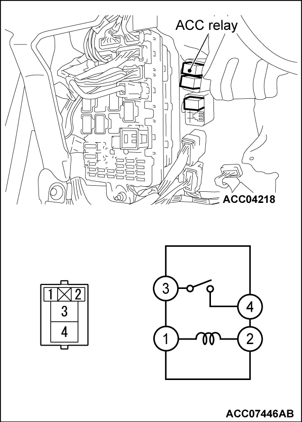
STEP 6. ACC relay check
Check that the ACC relay works normally.
 Replace the ACC relay.
|
Is the check result normal?
 Replace the ACC relay.
STEP 7. Resistance measurement at ACC relay connector (ground line)
(1) Disconnect the connector, and measure at the wiring harness side.
(2) Measure the resistance between the ACC relay connector (ground line) and the body ground.
OK: Continuity exists (2 Ω or less)
Is the check result normal?
STEP 8. Check of open circuit in ground line between the ACC relay connector and the body ground
Is the check result normal?
 Intermittent malfunction (Refer to GROUP 00 - How to Use Troubleshooting/Inspection Service Points - How to Cope with Intermittent Malfunction
  ).
). Repair the connector(s) or wiring harness.
STEP 9. Voltage measurement at ACC relay connector (ACC line).
(1) Disconnect the connector, and measure at the wiring harness side.
(2) Measure the voltage between the ACC relay connector (ACC line) and the body ground.
OK: System voltage
Is the check result normal?
STEP 10. Check of short and open circuit in ACC line between the OSS-ECU connector and the ACC relay connector
Is the check result normal?
 Replace the OSS-ECU.
 Repair the connector(s) or wiring harness.
STEP 11. Check of short and open circuit in power supply line between the junction block connector and the ACC relay connector
STEP 12. Voltage measurement at ETACS-ECU connector (ACCI line).
(1) Turn the engine switch from "LOCK" (OFF) position to "ON" position.
(2) Disconnect the connector, and measure at the wiring harness side.
(3) Measure the voltage between the ETACS-ECU connector (ACCI line) and the body ground.
OK: System voltage
Is the check result normal?
 Repair the wiring harness, ACCI line between the ETACS-ECU connector and the fusible link.
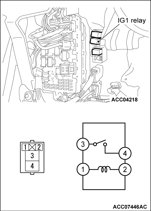
STEP 13. IG1 relay check
Check that the IG1 relay works normally.
 Replace the IG1 relay.
|
Is the check result normal?
 Replace the IG1 relay.
STEP 14. Resistance measurement at IG1 relay connector (ground line)
(1) Disconnect the connector, and measure at the wiring harness side.
(2) Measure the resistance between the IG1 relay connector (ground line) and the body ground.
OK: Continuity exists (2 Ω or less)
Is the check result normal?
STEP 15. Check of open circuit in ground line between the IG1 relay connector and the body ground
Is the check result normal?
 Intermittent malfunction (Refer to GROUP 00 - How to Use Troubleshooting/Inspection Service Points - How to Cope with Intermittent Malfunction
  ).
). Repair the connector(s) or wiring harness.
STEP 16. Voltage measurement at IG1 relay connector (IG1 line).
(1) Disconnect the connector, and measure at the wiring harness side.
(2) Measure the voltage between the IG1 relay connector (IG1 line) and the body ground.
OK: System voltage
Is the check result normal?
STEP 17. Check of short and open circuit in IG1 line between the OSS-ECU connector and the IG1 relay connector
Is the check result normal?
 Replace the OSS-ECU.
 Repair the connector(s) or wiring harness.
STEP 18. Voltage measurement at combination meter connector (IG1 line).
(1) Turn the engine switch from "LOCK" (OFF) position to "ON" position.
(2) Disconnect the connector, and measure at the wiring harness side.
(3) Measure the voltage between the combination meter connector (IG1 line) and the body ground.
OK: System voltage
Is the check result normal?
 Repair the wiring harness, IG1 line between the combination meter connector and the fusible link.
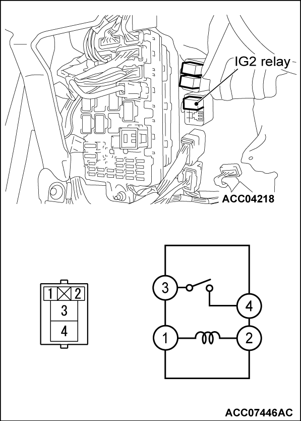
STEP 19. IG2 relay check
Check that the IG2 relay works normally.
 Replace the IG2 relay.
|
Is the check result normal?
 Replace the IG2 relay.
STEP 20. Resistance measurement at IG2 relay connector (ground line)
(1) Disconnect the connector, and measure at the wiring harness side.
(2) Measure the resistance between the IG2 relay connector (ground line) and the body ground.
OK: Continuity exists (2 Ω or less)
Is the check result normal?
STEP 21. Check of open circuit in ground line between the IG2 relay connector and the body ground
Is the check result normal?
 Intermittent malfunction (Refer to GROUP 00 - How to Use Troubleshooting/Inspection Service Points - How to Cope with Intermittent Malfunction
  ).
). Repair the connector(s) or wiring harness.
STEP 22. Voltage measurement at IG2 relay connector (IG2 line).
(1) Disconnect the connector, and measure at the wiring harness side.
(2) Measure the voltage between the IG2 relay connector (IG2 line) and the body ground.
OK: System voltage
Is the check result normal?
STEP 23. Check of short and open circuit in IG2 line between the OSS-ECU connector and the IG2 relay connector
Is the check result normal?
 Replace the OSS-ECU.
 Repair the connector(s) or wiring harness.
STEP 24. Check of short and open circuit in power supply line between the junction block connector and the IG2 relay connector
STEP 25. Voltage measurement at ETACS-ECU connector (IG2 line).
(1) Turn the engine switch from "LOCK" (OFF) position to "ON" position.
(2) Disconnect the connector, and measure at the wiring harness side.
(3) Measure the voltage between the ETACS-ECU connector (IG2 line) and the body ground.
OK: System voltage
Is the check result normal?
 Repair the wiring harness, IG2 line between the ETACS-ECU connector and the fusible link.
STEP 26. Using scan tool (M.U.T.-III), check data list.
(1)
| caution | To prevent damage to scan tool (M.U.T.-III), always turn the power supply mode of the engine switch to the OFF position before connecting or disconnecting scan tool (M.U.T.-III). |
(2) Turn the power supply mode of the engine switch to OFF.
(3) Operate the engine switch to change the power supply mode, and check that the data list display of ETACS-ECU is changed.
- When power supply mode is ACC or ON.
| ||||||||||
- When power supply mode is ON or START.
| ||||||||||
- When power supply mode is ON.
| ||||||||||
OK: Normal conditions are displayed for all the items.
Are the check result normal?
STEP 27. Recheck for diagnostic trouble code.
Check again if the DTC is stored in the OSS-ECU. Replace the ETACS-ECU.
(1) Erase the DTC.
(2) Turn the engine switch from "LOCK" (OFF) position to "ON" position.
(3) On completion, check that the DTC is stored again.
Is the DTC stored?
 Replace the ETACS-ECU.
 STEP 28. Recheck for diagnostic trouble code.
Check again if the DTC is stored in the OSS-ECU.
(1) Erase the DTC.
(2) Turn the engine switch from "LOCK" (OFF) position to "ON" position.
(3) On completion, check that the DTC is not stored again.
Is the diagnostic trouble code stored?
![[Previous]](../../../buttons/fprev.png)
![[Next]](../../../buttons/fnext.png)


