[Previous][Next]
REMOVAL AND INSTALLATION
 
 
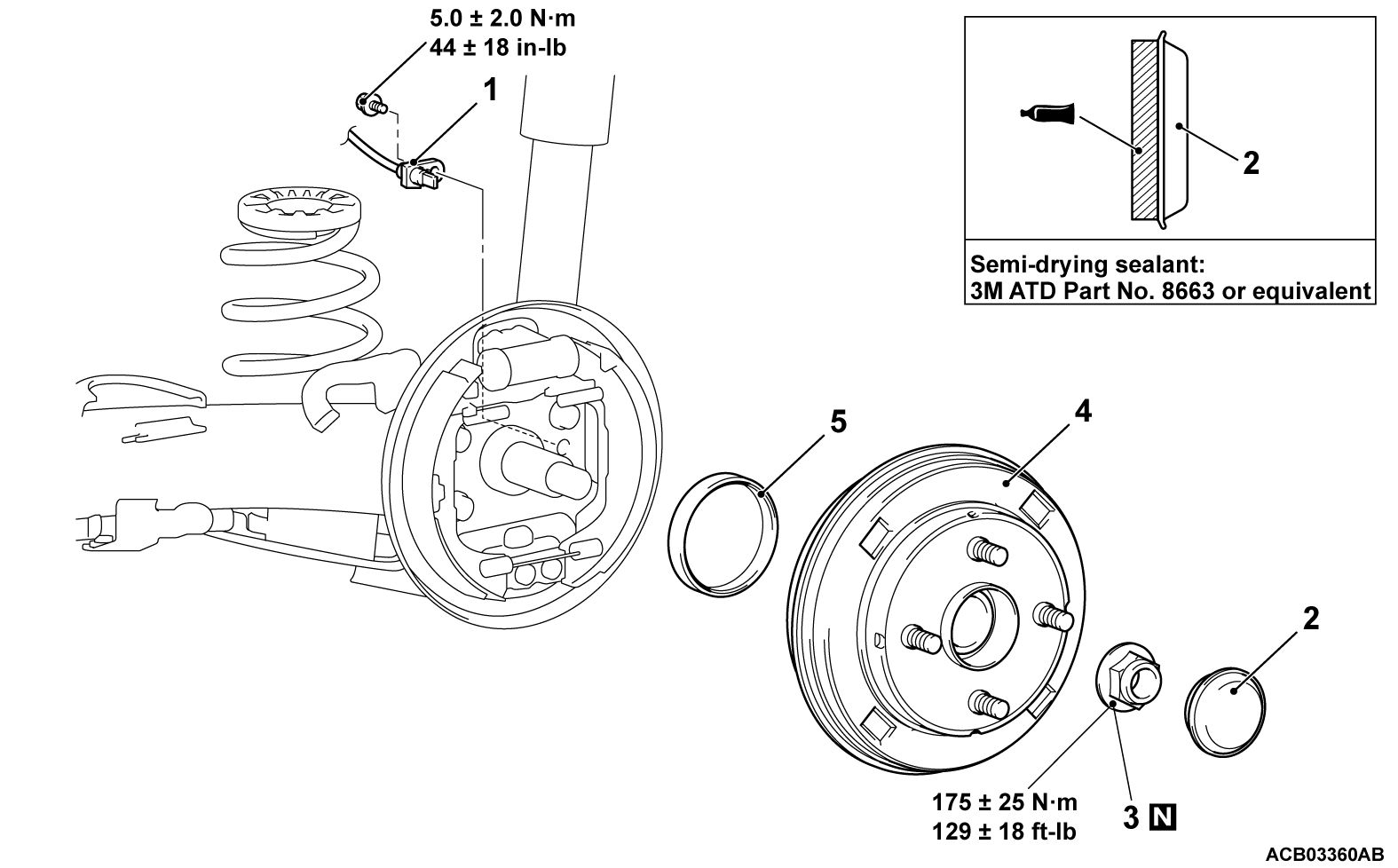
Removal steps
1.Rear wheel speed sensor (Refer to GROUP 35C - Wheel Speed Sensor )
2.Hub cap
<<A>>>>A<<3.Self-locking nut
<<B>>4.Rear wheel hub assembly
5.Pulse rotor
Required Special Tools:
  • MB991292: Axle shaft puller
 
 
REMOVAL SERVICE POINTS
 
 
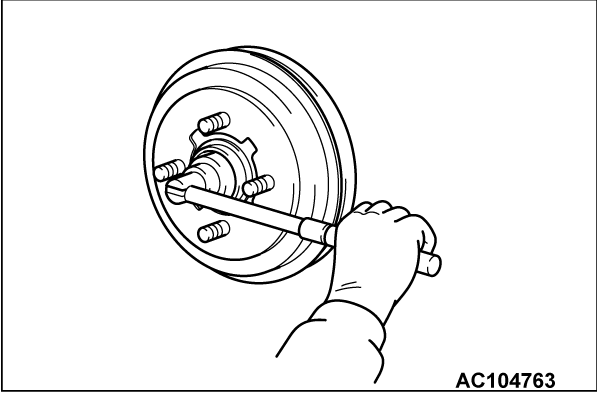
<<A>> SELF-LOCKING NUT REMOVAL
caution
  • Do not apply the vehicle weight to the wheel bearing while loosening the self-locking nut, or the wheel bearing will be damaged.
  • Use an manual tool only to remove the self-locking nut. (Do not use an electric or air tool).
  • Do not loosen the self-locking nut more than eight turns per one minute.


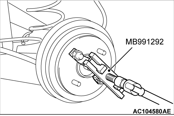
<<B>> REAR WEEL HUB ASSEMBLY REMOVAL
Use the following special tools to remove the rear wheel hub assembly.
  • Axle shaft puller (MB991292)


INSTALLATION SERVICE POINT
 
 
>>A<< SELF-LOCKING NUT INSTALLATION
caution
  • Before securely tightening the self-locking nuts, make sure there is no load on the wheel bearings. Otherwise the wheel bearing will be damaged.
  • Use an manual tool only to tighten the self-locking nut. (Do not use an electric or air tool).
  • Do not tighten the self-locking nut more than eight turns per one minute.
Tighten the self-locking nut to the specified torque.