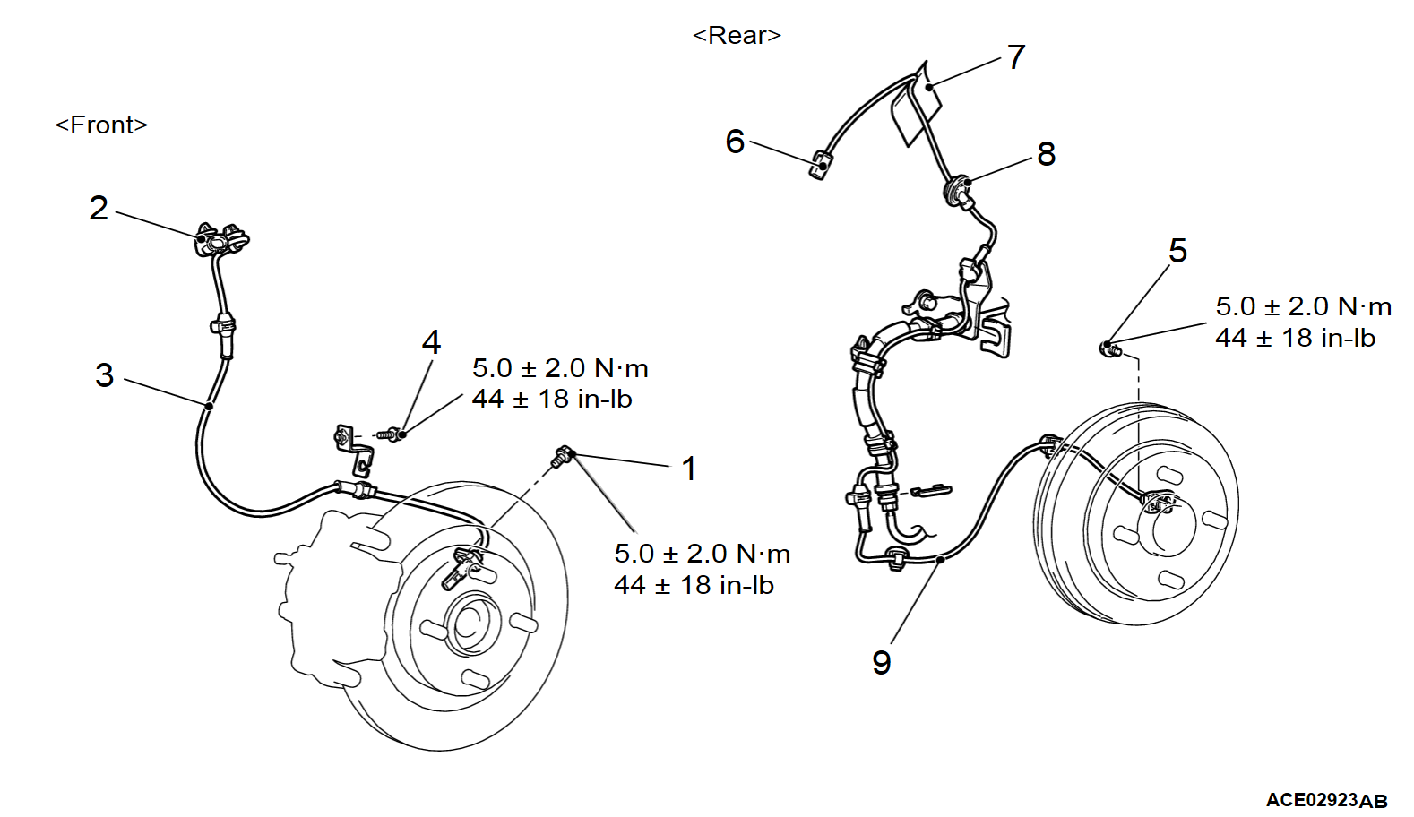
REMOVAL AND INSTALLATION
| caution | The vehicle speed detection encoder collects any metallic particle easily, because it is magnetized. Make sure that the encoder should not collect any metallic particle. Check that there is not any trouble prior to reassembling it. |
Pre-removal and post-installation operation |
| note | The encoder for detecting front wheel speed is a non-disassemble part integrated with the wheel bearing. |
REMOVAL SERVICE POINT
<<A>>REAR WHEEL SPEED SENSOR REMOVAL
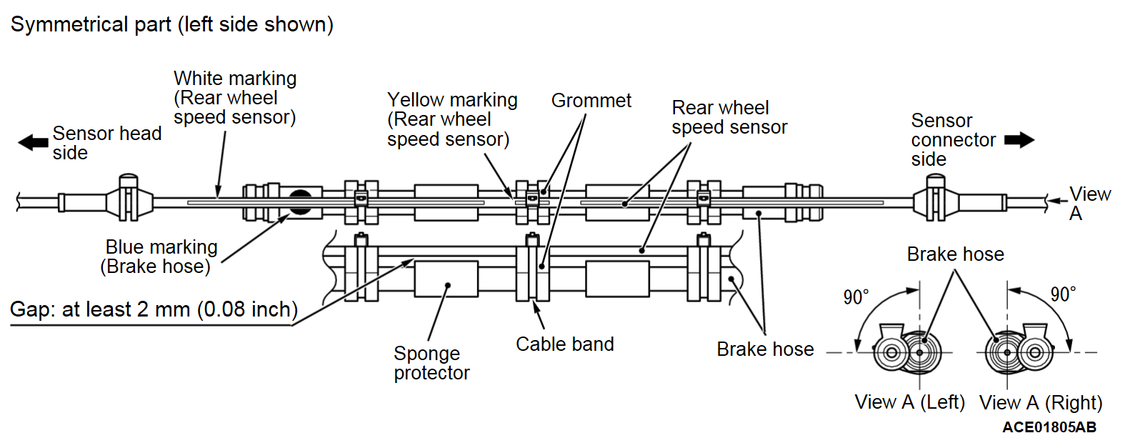
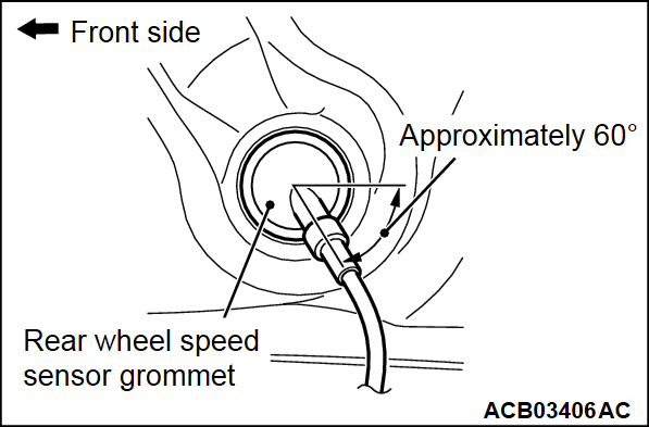
1. Before detaching the rear wheel speed sensor from the brake hose, mark position of the rear wheel speed sensor relative to the grommet.
2. Cut off the cable band to remove the rear wheel speed sensor.
INSTALLATION SERVICE POINT
>>A<< REAR WHEEL SPEED SENSOR INSTALLATION
| caution | Install the wheel speed sensor so that it is located on the outside of the vehicle. |
Assemble the rear wheel speed sensor to the brake hose according to the following steps.
| note | If a new rear wheel speed sensor is used, transfer the position mark from the old one to the new. |
1.
| caution | The head of the rear wheel speed sensor should face toward the blue marking on the brake hose. |
Align the rear wheel speed sensor with the grommet according to the position mark. Then route the brake hose, taking care not to kink the rear wheel speed sensor wiring harness.
2. Align the end of the yellow marking on the rear wheel speed sensor with the end of the grommet (sensor head side) at the middle of the brake hose.
3. Insert the rear wheel speed sensor wiring harness into the grommets so that the yellow marking and the white line on the sensor are visible.
4. Tighten the hose and the sensor wiring harness with a cable band at the grommet at the middle of the brake hose.
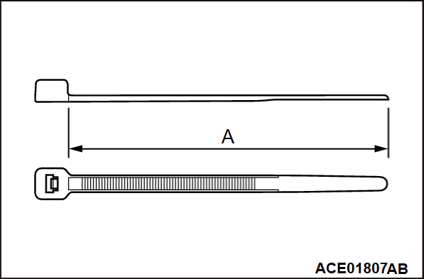
(1) Measure dimension (A) of the cable band.
(2) Assemble the cable band in the middle of the grommet.
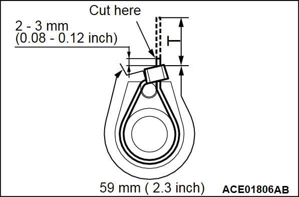
(3) Tighten the cable band so that the clamping distance (T) reaches the specified value as shown.
How to measure the clamping distance: T mm = A mm - 59 mm (2.3 inches)
(4) After the rear wheel speed sensor wiring harness is secured, cut off the end of cable band, leaving 2 - 3 mm (0.08 - 0.12 inch).
5. Avoid slack or drooping between the right and left grommets, and then tighten the wiring harness with a cable band.
| note | Repeat steps (3) and (4) for three cable band tightening positions. |
6. By pulling on the rear wheel speed sensor wiring harness, check that it is not displaced from the grommets.
7. Check that the gap between the sponge protector on the brake hose and the rear wheel speed sensor wiring harness is at least 2 mm (0.08 inch).
![[Previous]](../../../buttons/fprev.png)
![[Next]](../../../buttons/fnext.png)

