DTC P0705: Malfunction of Transmission Range Switch
DIAGNOSTIC FUNCTION
TCM monitors the signal from the transmission range switch, and determines if the abnormal input is present or not.
DESCRIPTIONS OF MONITOR METHODS
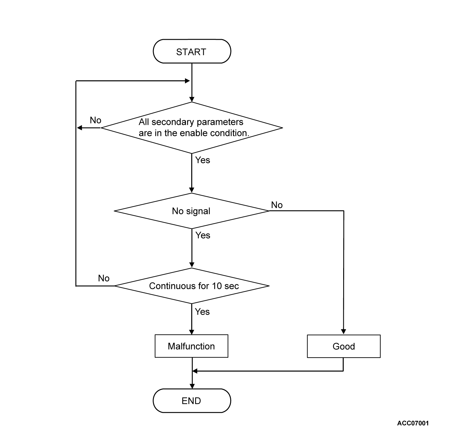
- TCM does not detects the transmission range switch input signal for 10 seconds when the vehicle speed is 3 km/h (2 mph) or more.
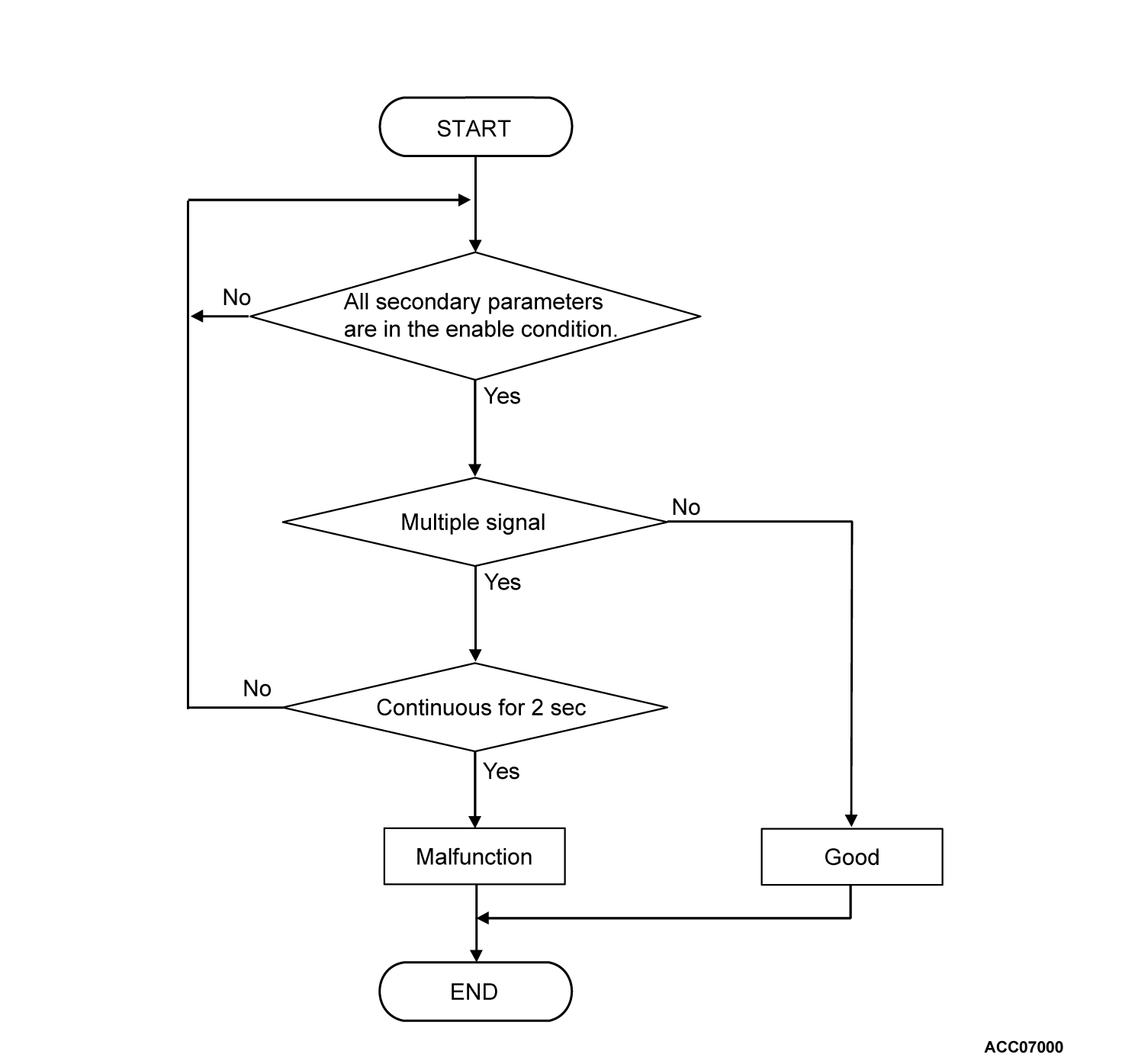
- TCM detects the multiple inputs from the transmission range switch for 2 seconds.
MONITOR EXECUTION
- Vehicle speed (no-transmission range switch signal input): 3km/h (2 mph) or more for 10 seconds continuously
- Vehicle speed (transmission range switch signal multiple input): No conditions
MONITOR EXECUTION CONDITIONS (OTHER MONITOR AND SENSOR)
Other Monitor (There is no temporary DTC stored in memory for the item monitored below)
- P0720: Malfunction of output speed sensor
Sensor (The sensor below is determined to be normal)
- Output speed sensor
DTC SET CONDITIONS
Check Conditions
- Voltage of battery: 10 volts or more.
- Voltage of battery: 16.5 volts or less.
Judgment Criteria
- TCM does not detects the transmission range switch input signal for 10 seconds when the vehicle speed is 3 km/h (2 mph) or more.
- TCM detects the multiple inputs from the transmission range switch for 2 seconds.
OBD-II DRIVE CYCLE PATTERN
The vehicle is driven for at least 20 seconds at the speed of 10km/h (6.2 mph) or more.
PROBABLE CAUSES
- Malfunction of the transmission range switch
- Improper adjustment of transaxle control cable
- Damaged wiring harness and connectors
- Malfunction of TCM
DIAGNOSIS
STEP 1. Check the following connector
- Transmission range switch connector
- TCM connector
Check the terminals for a contact status problem and internal short circuit.
Is the check result normal?
 Repair the defective connector(s).
STEP 2. Check for open circuit in INHP, INHR, INHN, INHD and INHL line between the transmission range switch connector and the TCM connector
STEP 3. Transmission range switch and control cable adjustment
STEP 4. Transmission range switch continuity check
STEP 5. Voltage measurement at TCM connector (INHP, INHR, INHN, INHD and INHL terminal)
(1) Connect the transmission range switch connector.
(2) Disconnect the TCM connector, and measure at the wiring harness side.
(3) Turn the ignition switch to the "ON" position.
(4) Measure the voltage at each terminal when the selector lever is moved to each range.
- At P range: Between the TCM connector (INHP terminal) and body ground
- At R range: Between the TCM connector (INHR terminal) and body ground
- At N range: Between the TCM connector (INHN terminal) and body ground
- At D range: Between the TCM connector (INHD terminal) and body ground
- At B range: Between the TCM connector (INHL terminal) and body ground
OK: 10 V or more
Is the check result normal?

- Repair the connector(s) or the wiring harness.
![[Previous]](../../../buttons/fprev.png)
![[Next]](../../../buttons/fnext.png)


