System Description
SYSTEM DIAGRAM
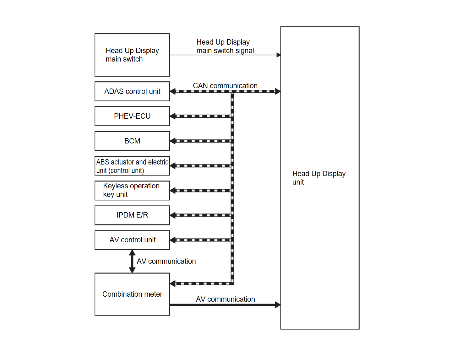
| Parts name | Description |
| Head Up Display unit | Refer to Head Up Display Unit . . |
| Head Up Display main switch | Refer to Head Up Display Main Switch . . |
| ADAS control unit 2 | Transmits the display signal of drive assistance and warning to the Head up Display unit via CAN communication. |
| PHEV-ECU | Transmits the ASCD status to the Head Up Display unit via CAN communication. |
| BCM | Transmits the following signals to the Head Up Display unit via CAN communication.
|
| ABS actuator and electric unit (control unit) | Transmits the odometer signal to the Head Up Display unit via CAN communication. |
| Keyless operation key unit | Transmits the user identification signal to the Head Up Display unit via CAN communication. |
| IPDM E/R | Transmits the battery voltage signal to the Head Up Display unit via CAN communication. |
| AV control unit | Transmits the key link activation status signal to the Head Up Display unit via CAN communication. |
| Combination meter |
|
Head Up Display Unit Input Signal
CAN communication signal
| Transmit unit | Signal name |
| ADAS control unit 2 | Display signal |
| PHEV-ECU | ASCD status signal |
| BCM | Auto ACC status signal |
| Vehicle status signal | |
| ABS actuator and electric unit (control unit) | Odometer signal |
| Keyless operation key unit | User identification signal |
| IPDM E/R | Battery voltage signal |
| AV control unit | Key link activation status signal |
| Combination meter | Vehicle speed display signal |
| HUD setting signal |
AV Communication signal (Combination meter → Head Up Display Unit)
| Transmit unit | Signal name |
| Combination meter | Navigation signal |
DESCRIPTION
- The Head Up Display (HUD) displays information on the vehicle speed and driving assistance system on the windshield glass, and supports safe driving by suppressing the burden due to the movement of the driver's eyes.
- The Head Up Display unit receives necessary signals from each ECU via CAN communication and local communication.
Operation
- When the electric motor switch is ON, pushing the main switch activates Head Up Display.
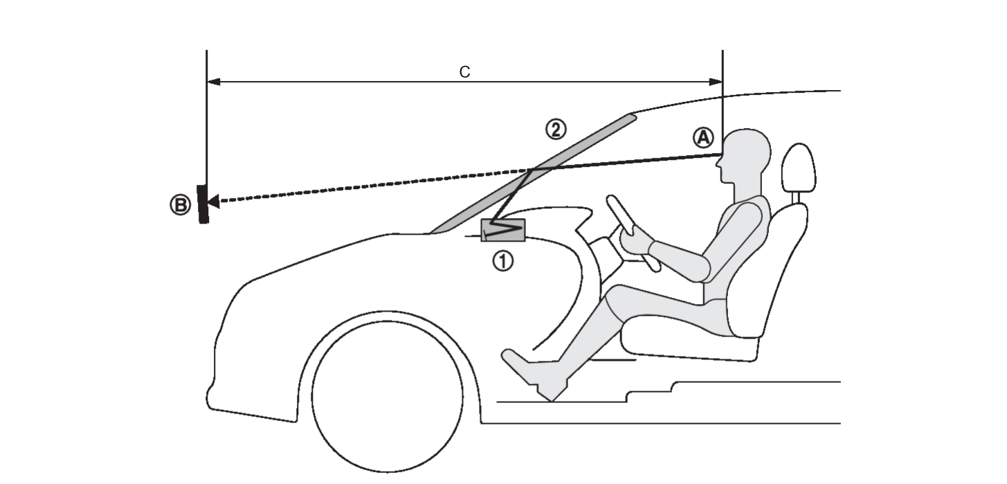
- Head Up Display projects display on the windshield glass.
- Image focus on 2.1 m (6.89 ft) from driver's eye point.
 | Head Up Display unit |  | Windshield glass |
 | Eye point |  | Virtual image display |
| C. | 2.1 m (6.89 ft) |
Structure
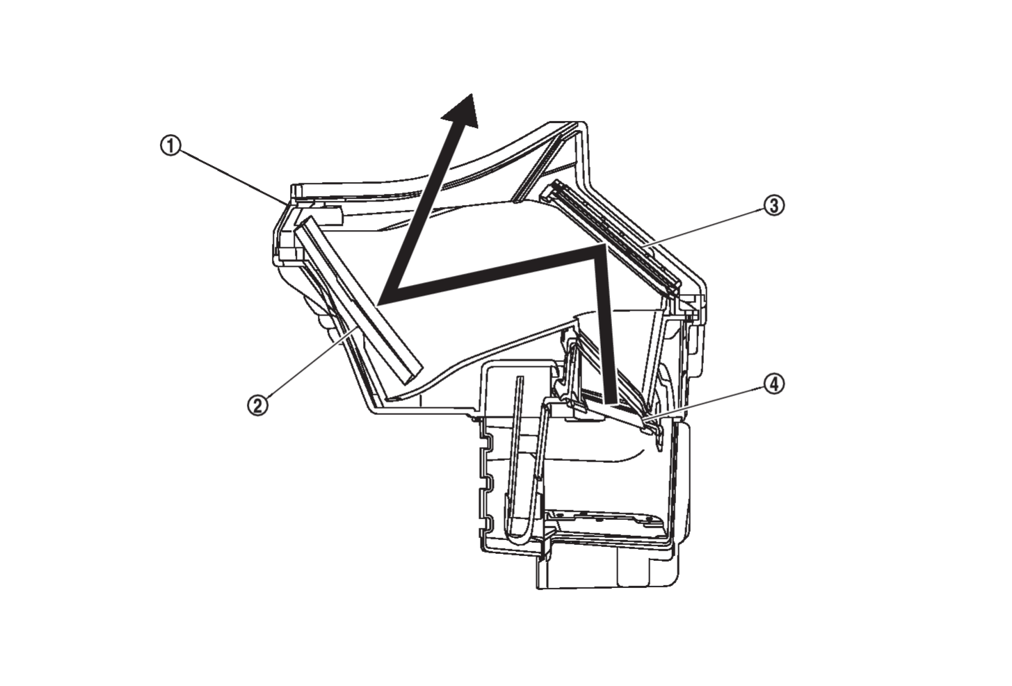
The Head Up Display unit projects the image to the windshield glass by reflecting the image of the TFT liquid crystal display on the concave mirror. Also, by manipulating the angle of the concave mirror, the projection position on the windshield glass can be adjusted.
 | Head Up Display unit |  | Concave mirror |  | Concave mirror |
 | TFT liquid crystal display | ||||
 | : Projection path |
Display Item
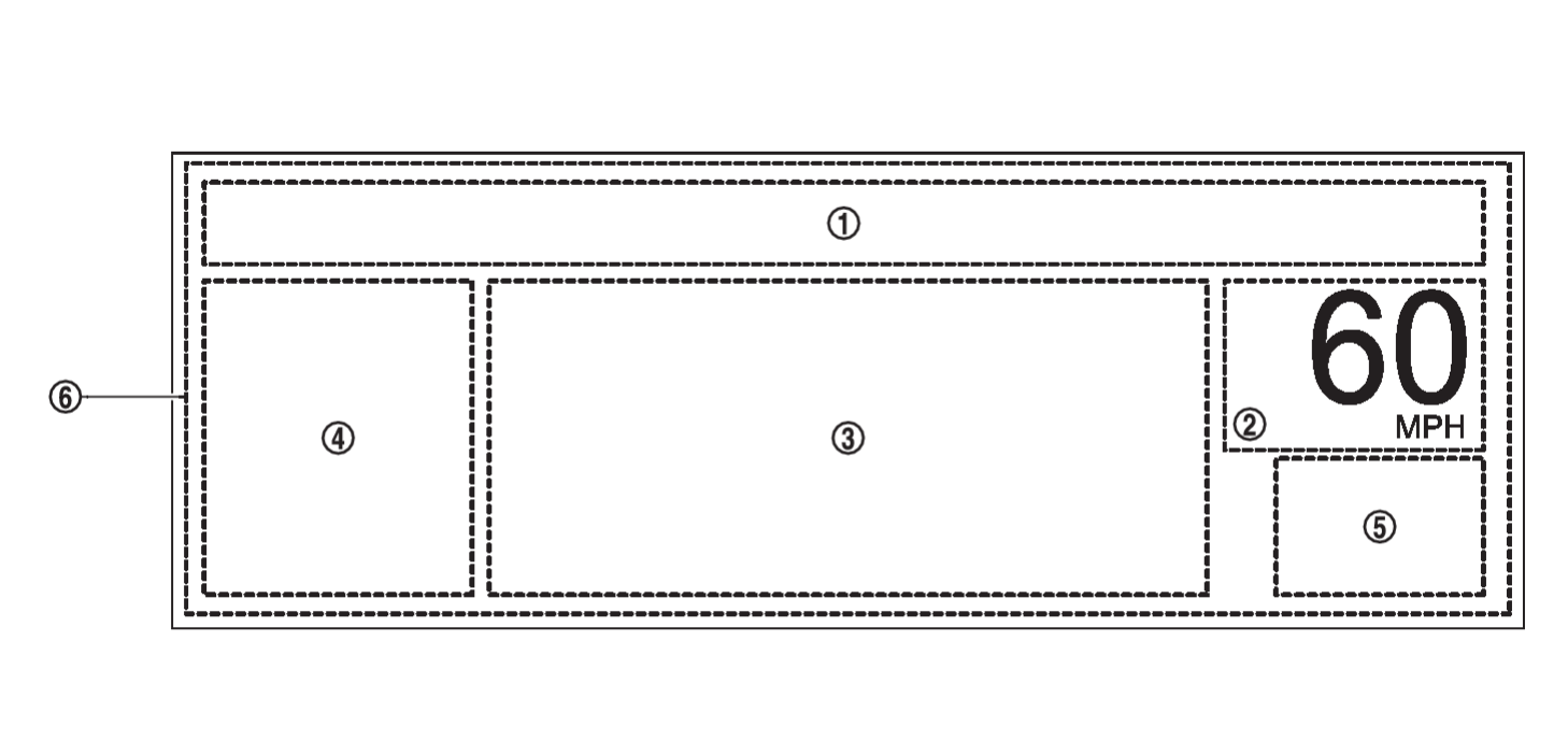
- The Head Up Display (HUD) can display one or more of the following features.
- The Head Up Display unit can cause an interrupt on the HUD display to indicate a warning, based on signals received from each unit.
| No. | Display | Description | |
 | Message display |
| |
 | Vehicle speed display | Always display the vehicle speed | |
 | Driving Aids | ASCD display | Displays setting vehicle speed during ASCD operation |
| ACC display | Displays information on setting vehicle speed and presence/absence of preceding vehicle during ACC operation | ||
| MI PILOT Assist system display | Displays setting MI PILOT Assist system status during MI PILOT Assist system operation | ||
| LDW system display | Displays LDW system display during LDW system operation | ||
| LDP system display | Display LDP system display during LDP system operation | ||
| PFCW system display | Display PFCW display during PFCW operation | ||
 | Turn by Turn display | Display arrows at intersection with navigation guidance and guide traveling direction | |
 | TSR system display | Display TSR system display during TSR system operation | |
 | Interrupt display | MI PILOT Assist system warning display | Display MI PILOT Assist system display during MI PILOT Assist system operation |
| AEB warning display | Display AEB warning display during AEB operation | ||
| Turn by Turn display | Display arrows at intersection with navigation guidance and guide traveling direction | ||
| Audio operation display | Display audio operation display during audio switch operation | ||
| note |
|
Automatic Dimming Function
The Head Up Display unit reads the illuminance sensor value and adjusts the brightness of the display automatically.
| note | The brightness of the display can be manually adjusted on the combination meter setting screen. Refer to Switch Name and Function . . |
![[Previous]](../../../buttons/fprev.png)
![[Next]](../../../buttons/fnext.png)


